Special cooling device with cold water circulation effect and used for metal production quenching

A cold water circulation and cooling device technology, applied in quenching devices, manufacturing tools, heat treatment equipment, etc., can solve the problem that the cooling device does not have the function of cold water circulation, and achieve the effect of saving time and improving practicability

Inactive Publication Date: 2018-12-14
饶品魁
View PDF1 Cites 1 Cited by
  • Summary
  • Abstract
  • Description
  • Claims
  • Application Information

AI Technical Summary

Problems solved by technology

[0004] Aiming at the deficiencies of the prior art, the present invention provides a special cooling device for metal production and quenching with cold water circulation, which has the advantages of cold water circulation function, etc., and solves the problem that the existing cooling device does not have the function of cold water circulation

Method used


Image

  • Special cooling device with cold water circulation effect and used for metal production quenching
  • Special cooling device with cold water circulation effect and used for metal production quenching
  • Special cooling device with cold water circulation effect and used for metal production quenching

Examples


Embodiment 2

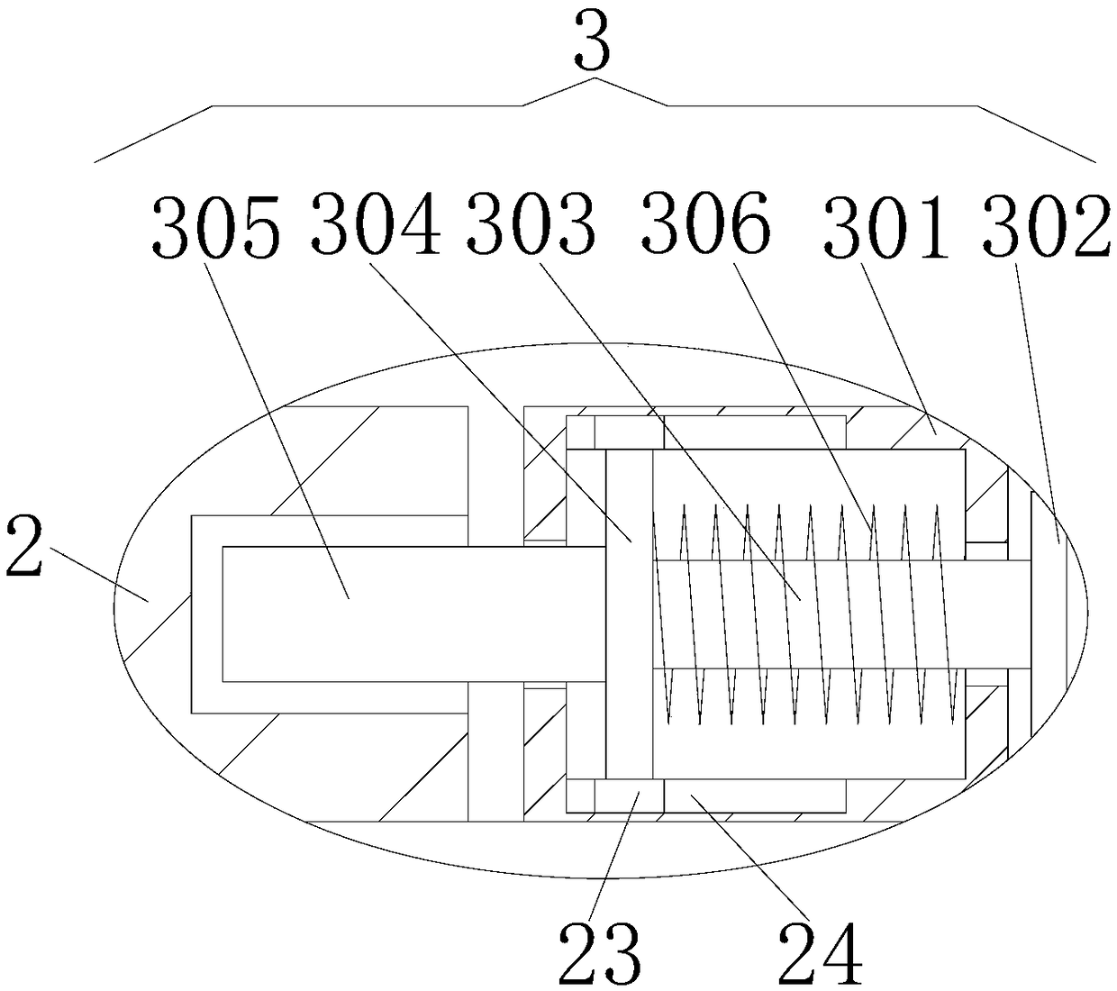
[0031] Embodiment 2: The difference from Embodiment 1 is that the limit mechanism 3 includes a transmission box 301, a disk 302 is arranged on the right side of the transmission box 301, a pull rod 303 is fixedly connected to the left side of the disk 302, and the left end of the pull rod 303 runs through The transmission box 301 extends to the inside of the transmission box 301 and is fixedly connected with a moving column 304. The top and bottom of the moving column 304 are slidingly connected with the top and bottom of the inner wall of the transmission box 301 respectively, and the left side of the moving column 304 is fixedly connected with a clamping rod 305. , the left end of the clamping rod 305 runs through the cover plate 2 and extends to the inside of the cover plate 2, the surface of the pull rod 303 is covered with a spring 306, the left end of the spring 306 is fixedly connected with the moving column 304, and the right end of the spring 306 is fixedly connected wi...

Embodiment 3

[0032] Embodiment 3: The difference from Embodiment 2 is that the top and bottom of the moving column 304 are fixedly connected with a slider 23, and the top and bottom of the inner wall of the transmission box 301 are provided with a chute 24, and the chute 24 and the slider 23 slide Connection, by setting the slider 23 and the chute 24, the slider 23 can be driven to move left and right when the moving column 304 moves left and right, thereby avoiding the contact between the moving column 304 and the transmission box 301, and preventing friction between the transmission box 301 and the moving column 304 Compared with the guide rail structure on the market, this structure can effectively prevent the friction between the transmission box 301 and the moving column 304, and does not occupy the internal space of the transmission box 301. The guide rail structure on the market is generally fixed inside the transmission box 301. Then move the moving column 304 to the inside of the g...

Embodiment 4

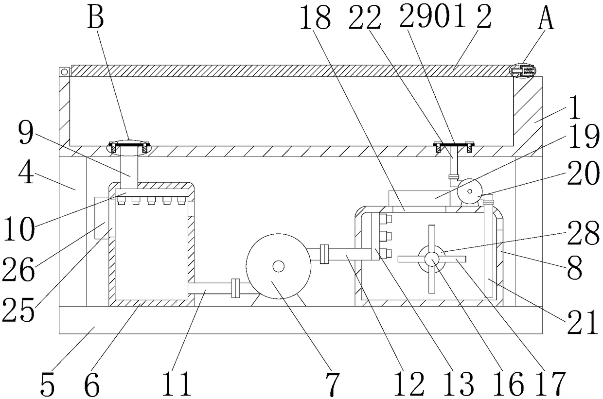
[0033] Embodiment 4: The difference with Embodiment 1 is that the top of the storage box 6 left side is provided with a through hole 25, and the left side of the through hole 25 is provided with a second exhaust fan 26, and the air outlet of the second exhaust fan 26 is connected with the through hole. 25 communicates, by setting the through hole 25 and the second exhaust fan 26, the user can open the second exhaust fan 26, the second exhaust fan 26 sends the cold wind into the storage box 6 through the through hole 25, and the storage box 6 is cooled by the cold wind. Compared with the market, there is no such structure. When the water is cooled, the structure is cooled by the second exhaust fan 26, which can save the subsequent cooling time and improve the cooling effect.


PUM


Abstract

The invention discloses a special cooling device with a cold water circulation effect and used for metal production quenching. The special cooling device with the cold water circulation effect and used for metal production quenching comprises a water cooling device, the left side of the top of the water cooling device is movably connected with a cover plate, and the right side of the bottom of thecover plate makes contact with the water cooling device. Due to the arrangement and cooperation of the water cooling device, the cover plate, a limiting mechanism, a transmission box, a disc, a pullrod, a movable post, a clamping rod, a spring, supporting legs, a bottom plate, a storage tank, a first water pump, a cooling tank, a water feeding pipe, a first sprayer, a first water drawing pipe, apositioning pipe, a second sprayer, a positioning block, a motor, a rotating rod, a stirring rod, a heat dissipation hole, a first exhaust fan, a second water pump, a second water drawing pipe, a cold water pipe, a filtering mechanism, a filtering net and bolts, water is stirred through the stirring rod, heat dissipation is conducted on the water in the cooling box through the first exhaust fan,and then the second water pump and the second water drawing pipe are matched to convey the cooled water into the water cooling device, so that the cold water circulation effect is achieved.

Description

technical field [0001] The invention relates to the technical field of metal quenching and cooling devices, in particular to a special cooling device for metal production and quenching equipped with cold water circulation. Background technique [0002] Metal is a material with luster (that is, strong reflection of visible light), high ductility, easy conduction of electricity, and heat conduction. Most of the metal elements on the earth exist in nature in a compound state. This is because the chemical properties of most metals are relatively active, and only a few metals such as gold and silver exist in a free state. Metals exist widely in nature and are widely used in daily life. They are very important and most widely used substances in modern industry. When producing metals, quenching devices are required. Quenching is to heat steel to the critical temperature Ac3 (sub eutectoid steel) or Ac1 (hypereutectoid steel) above the temperature, keep it warm for a period of tim...

Claims


Application Information

Patent Timeline
Patent Type & Authority Applications(China)
IPC IPC(8): C21D1/64C21D9/00C22F1/00
CPCC21D1/64C21D9/0062C22F1/002
Inventor 饶品魁
Owner 饶品魁
Why Eureka
Try Eureka