Directional windowing horizontal drilling device and process method

A technology of horizontal drilling and process method, which is applied in directional drilling, drill pipe, drill pipe and other directions, which can solve the problem of easy deviation from the original track and achieve the effect of keeping the track straight

Active Publication Date: 2018-12-14
DAQING JINGTAI PETROLEUM ENG TECH
View PDF6 Cites 2 Cited by
  • Summary
  • Abstract
  • Description
  • Claims
  • Application Information

AI Technical Summary

Problems solved by technology

[0003] The first object of the present invention is to provide a horizontal drilling device with directional windows, which overcome

Method used


Image

  • Directional windowing horizontal drilling device and process method
  • Directional windowing horizontal drilling device and process method
  • Directional windowing horizontal drilling device and process method

Examples


Embodiment 1

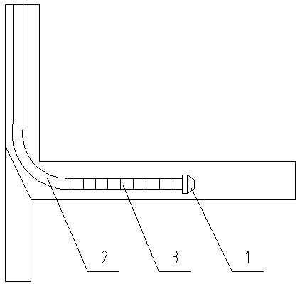
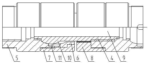
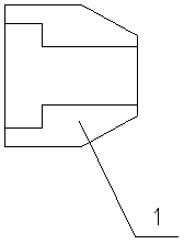
[0019] figure 1 It is a structural schematic diagram of the present invention, figure 2 Yes figure 1 Enlarged view of the flexible straightening unit in, image 3 It is an enlarged schematic view of the drill bit. As shown in the figure, a directional window-opening horizontal drilling device includes a drill bit 1 and a flexible drill rod 2, and multiple flexible straightening units are connected between the drill bit 1 and the flexible drill rod 2. 3. Each flexible straightening unit 3 includes an inner core 4, a main body 5, a pressure cap 6, a large spare cap 7 and a small spare cap 8, the main body 5 is set on the inner core 4, the inner core 4 is hollow, and a water outlet is formed in the center Channel 9, when drilling, the high-pressure water flow passes through the water passage, and then sprays out from the water outlet of the drill bit. The outer wall of the inner core 4 is provided with a spherical protrusion 10, and the surface of the spherical protrusion 10 ...

Embodiment 2

[0022] A process method for a directional window-opening horizontal drilling device, characterized in that the method comprises the following steps:

[0023] (1) First anchor the oblique device in the casing, and then open a window on the opposite casing of the oblique device;

[0024] (2) Use the skewer to complete a 90° turn in a short distance, and then use the flexible horizontal drilling tool to extend the horizontal direction of the target layer to drill to the limit of the footage, and the drill bit drives multiple flexible straightening units and flexible drill pipes to perform horizontal extension drilling In, the water flows directly to the drill bit through the water passage, and then sprays out through the water outlet on the drill bit. There is an area difference between the water outlet of the drill bit and the inner diameter, which causes the water flow to generate a pressure difference. Under the action of the pressure difference, the main body from the inner co...


PUM

PropertyMeasurementUnit
Depthaaaaaaaaaa
Thicknessaaaaaaaaaa

Abstract

The invention relates to a directional windowing horizontal drilling device. Multiple flexible straightening units are connected between a drill bit and a flexible drill pipe. For each flexible straightening unit, a body sleeves a hollow inner core, a water passage is formed in the center of the inner core, a spherical protrusion is arranged on the outer wall of the inner core, multiple small steel balls are installed on the surface of the spherical protrusion, the small steel balls are evenly arranged along the circumferential surface of the spherical protrusion, the bottom of the spherical protrusion is contracted to a straight surface, and a tight fit can be formed between the straight surface and the body; the top end of the body is sleeved with a pressure cap, the body and the pressure cap are provided with arc concave surfaces matching the spherical protrusion on the inner walls thereof, the spherical protrusion is right in the arc concave surfaces, strip-shaped grooves are formed in the center of the arc concave surfaces, the small steel balls are right in the strip-shaped grooves, and the length of the strip-shaped grooves is equal to the length of the bottom straight surface of the spherical protrusion; and the body and the pressure cap are pressed with a large spare cap, and the bottom end of the body is pressed with a small spare cap. The directional windowing horizontal drilling device can ensure that the trajectory of a horizontal wellbore is kept straight in the process of drilling.

Description

technical field [0001] The invention belongs to the field of oil field equipment and relates to a directional window opening horizontal drilling device and a process method. Background technique [0002] During the development of oil and gas fields, due to the characteristics of reservoir formation, nearly 30% of the remaining oil reservoirs will be behind faults or in oil layers that cannot be displaced. These oil reservoirs cannot be exploited by conventional techniques. People call it the side body, the potato layer, and so on. With the continuous upgrading of oilfield production technology, technologies such as volume fracturing, T-shaped drilling, radial drilling, and ultra-short radius horizontal drilling have emerged for such reservoirs. The disadvantages such as not being able to reach the depth of the remaining reservoir. Because the currently used flexible drill pipe is guided into the formation horizontally under the guidance of the skewer, but because the hardn...

Claims


Application Information

Patent Timeline
IPC IPC(8): E21B17/20E21B7/04
CPCE21B7/04E21B17/20
Inventor 张亚胜
Owner DAQING JINGTAI PETROLEUM ENG TECH
Why Eureka
Try Eureka