Air cylinder structure and locomotive

A cylinder and gas technology, applied in mechanical equipment, fluid pressure actuation devices, servo motors, etc., can solve problems such as the inability to realize the cylinder buffer function.

Pending Publication Date: 2018-12-14
VANGUARD BEIJING TECH DEV
View PDF0 Cites 2 Cited by
  • Summary
  • Abstract
  • Description
  • Claims
  • Application Information

AI Technical Summary

Problems solved by technology

[0003] Therefore, the technical problem to be solved by the present invention is to overcome the defect that the conventional intake and exhaust throttling of the oscillating cylinder in the prior art cannot realize the buffer function of the cylinder under the instantaneous control operation mode, thereby providing a cylinder structure that can realize the buffer function

Method used


Image

  • Air cylinder structure and locomotive
  • Air cylinder structure and locomotive
  • Air cylinder structure and locomotive

Examples


Embodiment approach

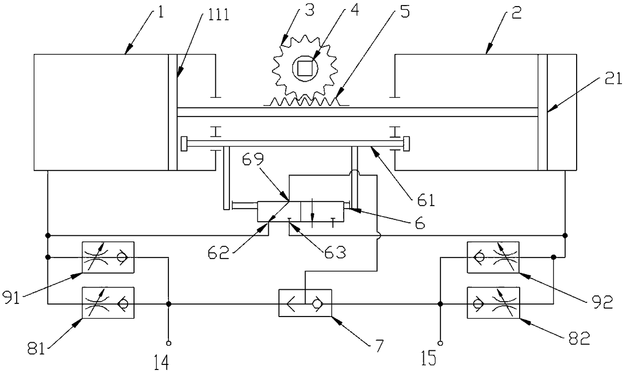
[0043] Such as figure 1 A specific implementation of the shown cylinder structure includes:

[0044] The first cylinder 1 and the second cylinder 2, the first cylinder is provided with a first piston assembly 111, the second cylinder is provided with a second piston assembly 21, the first piston assembly 111 and the second The piston assembly 21 is linked, the first cylinder 1 is provided with a first air inlet 14 and a first exhaust throttle valve 81, and the second cylinder 2 is provided with a second exhaust throttle valve 82;

[0045] The buffer valve 6 is connected with the first air inlet 14, and the first air inlet 14 is connected with a gas source, and the gas flowing in from the first air inlet 14 is divided into two paths, and the first path enters In the first cylinder 1, the second path enters the buffer valve 6;

[0046]The buffer valve 6 has a first position where the gas inside flows into the first cylinder 1 and flows into the second cylinder 2 under the acti...


PUM


Abstract

The invention relates to an air cylinder structure and a locomotive, and particularly belongs to the pneumatic technical field. The air cylinder structure comprises a first air cylinder, a second aircylinder and a buffer valve, a first piston assembly is arranged in the first air cylinder, a second piston assembly is arranged inside the second air cylinder, the first piston assembly and the second piston assembly are in linkage, the first air cylinder is provided with a first gas inlet and a first exhaust throttling valve, the second air cylinder is provided with a second exhaust throttling valve, the buffer valve is connected with the first gas inlet, the first gas inlet communicates with a gas source, gas flowing from the first gas inlet is divided into two paths of gas, the first pathof gas enters the first air cylinder, and the second path of gas enters the buffer valve. According to the air cylinder structure, the defect that in the case of a swing air cylinder in the prior artunder a transient operation mode, an air cylinder buffering function cannot be achieved through conventional gas inlet and exhaust throttling is overcome.

Description

technical field [0001] The invention relates to a cylinder structure and a locomotive, specifically belonging to the field of pneumatic technology. Background technique [0002] As a mechanism that reciprocates and rotates within a certain angle range, the swing cylinder is usually used to drive the opening and closing action of the high-voltage grounding switch or similar equipment on the rolling stock. Due to the limitation of installation space and structure, the cylinder volume and piston stroke of the oscillating cylinder used on the existing rolling stock are generally too small. Therefore, in the instantaneous control operation mode, the conventional intake and exhaust throttling cannot realize the cylinder buffer function, resulting in extra impact on the external devices such as the high-voltage grounding switch during the opening and closing operation, causing damage to the device and affecting the locomotive Safe operation of vehicles. Contents of the invention...

Claims


Application Information

Patent Timeline
Patent Type & Authority Applications(China)
IPC IPC(8): F15B15/14F15B15/20F15B15/22F15B11/16F15B13/06
CPCF15B15/1404F15B11/16F15B13/06F15B15/1423F15B15/149F15B15/202F15B15/204F15B15/22
Inventor 刘树坤潘高
Owner VANGUARD BEIJING TECH DEV
Why Eureka
Try Eureka