
Active clamping forward-and-flyback circuit capable of starting or stopping synchronous rectification

A synchronous rectification, forward and flyback technology, which is applied in the direction of output power conversion device, DC power input conversion to DC power output, electrical components, etc., can solve the problems of main tube withstand voltage breakdown, main tube impact, etc., and achieve simple circuit principle Effect

Inactive Publication Date: 2013-09-11
嘉善中正电子科技有限公司
View PDF4 Cites 3 Cited by
  • Summary
  • Abstract
  • Description
  • Claims
  • Application Information

AI Technical Summary

Problems solved by technology

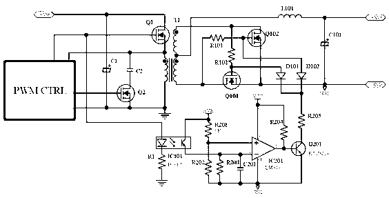
[0003] The present invention is aimed at the problem that a large resonance voltage will be generated on the main tube after the synchronous rectification of the active clamp circuit, which will cause breakdown when the main tube withstand voltage is insufficient, and proposes an active clamp with a synchronous rectification shutdown function It is a positive and flyback circuit, which realizes the drive cut-off of the synchronous rectifier on the secondary side after collecting the main driving signal of the primary side after isolation
Solved the impact of the resonant voltage on the main tube when the secondary side energy is fed back

Method used


Image

  • Active clamping forward-and-flyback circuit capable of starting or stopping synchronous rectification
  • Active clamping forward-and-flyback circuit capable of starting or stopping synchronous rectification
  • Active clamping forward-and-flyback circuit capable of starting or stopping synchronous rectification

Examples


Embodiment Construction

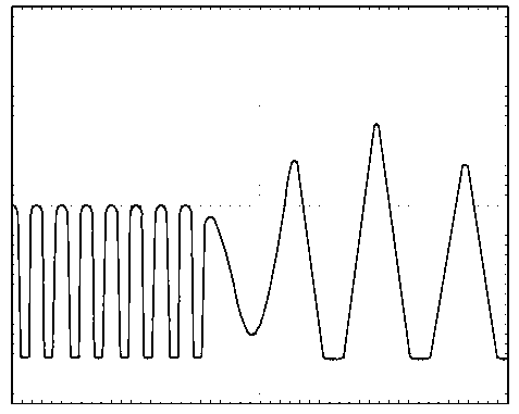
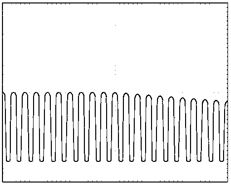
[0013] Such as figure 2 The shown active clamp forward and flyback circuit diagram with synchronous rectification shutdown function, on the main circuit in charge of the drive circuit, directly drives the optocoupler IC101 through a simple resistor, and the output part of the optocoupler is connected to the comparator IC201. It is to judge whether the main driving signal on the primary side exists, and if it exists, it will output a low level, and the work of the synchronous rectifier will not be disturbed. If the main driver of the primary side is turned off, the comparator immediately outputs a high potential to drive Q201 and then forcibly turns off the pair of synchronous rectifiers. After the synchronous rectifier is turned off, the secondary side energy cannot be fed back to the primary side. The main voltage of the primary side is attenuated and oscillating, and no additional stress impact will be generated, such as image 3 The voltage waveform diagram when the main...


PUM


Abstract

The invention relates to an active clamping forward-and-flyback circuit capable of starting or stopping synchronous rectification. According to the active clamping forward-and-flyback circuit capable of starting or stopping the synchronous rectification, an acquisition and isolating circuit and a comparison and driving circuit are added between a primary edge and a secondary edge, the output of a main tube driving circuit of a main circuit is connected with the comparison and driving circuit through the acquisition and isolating circuit, and the comparison and driving circuit is connected with a synchronous rectification tube control end on the secondary edge. According to the active clamping forward-and-flyback circuit capable of starting or stopping the synchronous rectification, the driving stopping of a synchronous rectification tube is achieved on the secondary edge, and the synchronous stopping of the synchronous rectification of the secondary edge is guaranteed when a main tube on the primary edge is switched off. The active clamping forward-and-flyback circuit capable of starting or stopping the synchronous rectification has the advantages that the problem that the main tube is impacted by resonance voltage when energy of the secondary edge of an original active clamping circuit is recovered is solved, the principle of the circuit is simple and reasonable, and other functions and indexes of the circuit will not be affected.

Description

technical field [0001] The invention relates to a switching power supply circuit, in particular to an active clamp forward and flyback circuit with a synchronous rectification shutdown function. Background technique [0002] In the design of switching power supply with medium power, using active clamp circuit as the main circuit design is a topology with very ideal performance in principle. In addition to realizing the soft-switching characteristics of the main primary side, it is also possible to simply realize the self-driving of the synchronous rectifier on the secondary side. However, this topology whose steady-state characteristics are close to ideal has relatively fatal dynamic characteristics. Since the energy can be returned from the secondary side to the primary side after the synchronous rectification is realized, the output energy can be fed back to the primary side when the main tube is turned off and the auxiliary tube is continuously turned on. At this time, a...

Claims


Application Information

Patent Timeline
Patent Type & Authority Applications(China)
IPC IPC(8): H02M3/335
CPCY02B70/10
Inventor 陶敬恒张红彬
Owner 嘉善中正电子科技有限公司
Learn More