
Gear tooth groove internal diameter measuring instrument of internal gear

A technology of internal gears and measuring instruments, which is applied in the direction of mechanical diameter measurement, etc., can solve the problems of uneven placement of internal gears, small parts, and large errors in the length of the inner diameter M of the tooth groove, so as to improve accuracy and facilitate judgment Effect

Pending Publication Date: 2018-12-14
DONGGUAN TIANLONG AKEDA ELECTRONICS CO LTD
View PDF11 Cites 1 Cited by
  • Summary
  • Abstract
  • Description
  • Claims
  • Application Information

AI Technical Summary

Problems solved by technology

[0004] This method has the following disadvantages: 1. When the measuring personnel move the probes, they cannot ensure that the two measuring probes are embedded in the tooth grooves on the same diameter, resulting in a small length of the inner diameter M of the tooth grooves; 2. The measuring personnel place the When the internal gear is uneven, there will be a height difference between the two probes, resulting in a large length of the inner diameter M of the tooth groove; 3. The probe cannot match the structure of the tooth groove, resulting in a large error in the length of the inner diameter M of the tooth groove ; 4. The parts are small in size, and it is time-consuming and labor-intensive to observe the insertion of the probe into the tooth groove by naked eyes

Method used


Image

  • Gear tooth groove internal diameter measuring instrument of internal gear
  • Gear tooth groove internal diameter measuring instrument of internal gear
  • Gear tooth groove internal diameter measuring instrument of internal gear

Examples


Embodiment Construction

[0025] In order to make the object, technical solution and advantages of the present invention clearer, the present invention will be further described in detail below in conjunction with the accompanying drawings.

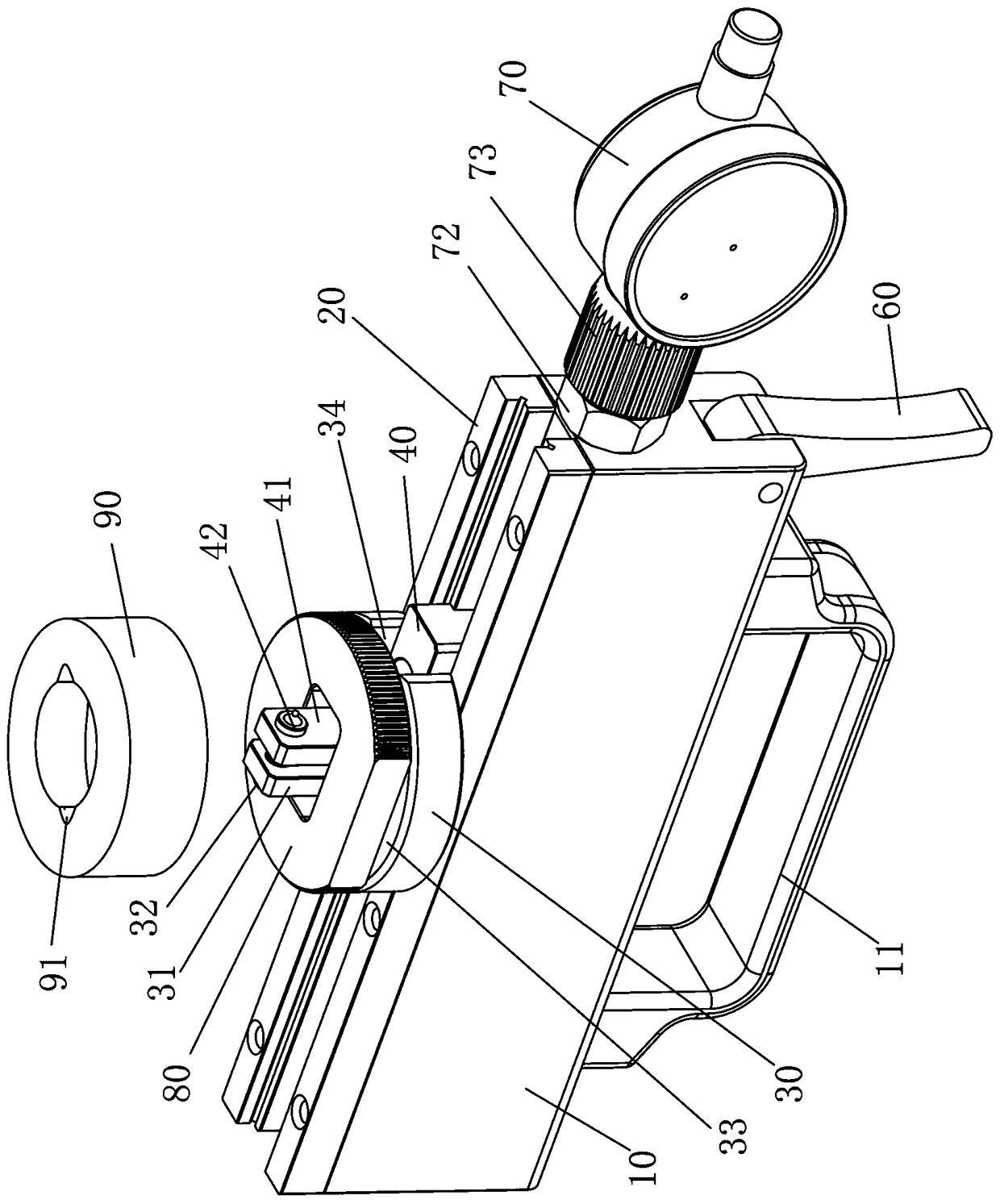
[0026] Such as Figure 3-5 As shown, the embodiment provided by the present invention is a tooth groove internal diameter measuring instrument of an internal gear, which includes a bracket 10, a linear guide rail 20, a fixed block 30, a moving block 40, a transmission rod, a trigger 60 and a digital display percentage Table 70.

[0027] The linear guide rail 20 is installed on the bracket 10, the fixed block 30 is fixedly installed on the linear guide rail 20, the moving block 40 is slidably installed on the linear guide rail 20 and is located in front of the fixed block 30; The upper end of the block 40 is provided with a moving measuring column 41 .

[0028] The digital display dial indicator 70 is installed on the front end of the bracket 10 through the insta...


PUM


Abstract

The invention provides a gear tooth groove internal diameter measuring instrument of an internal gear. The gear tooth groove internal diameter measuring instrument of the internal gear comprises a supporting seat, a linear guide, a fixed block, a moving block, a transmission rod, a trigger and a digital display dial indicator. The linear guide is installed on the supporting seat, the fixed block is fixedly installed on the linear guide, and the moving block is installed on the linear guide in a sliding mode and is located in the front part of the fixed block. A fixed measuring column is arranged at the upper end of the fixed block, and a moving measuring column is arranged at the upper end of the moving block. The digital display dial indicator is installed on the front end of the supporting seat through an installation assembly, and a measuring rod of the digital display dial indicator is inserted into the supporting seat. The rear end of the transmission rod is connected with the front end of the moving block, the middle portion of the transmission rod is hinged at the upper end of the trigger, and the front end of the transmission rod abuts against the rear end of the measuringrod. The lower end of the trigger is buckled and pressed, and the moving block is driven to move forward along the linear guide by the transmission rod, so that the fixed measuring column is far awayfrom the moving measuring column. According to the gear tooth groove internal diameter measuring instrument of the internal gear, measuring is accurate, and time and labor are saved.

Description

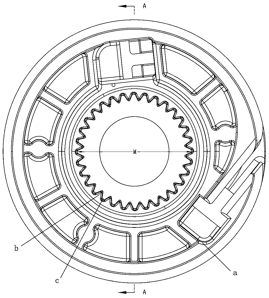
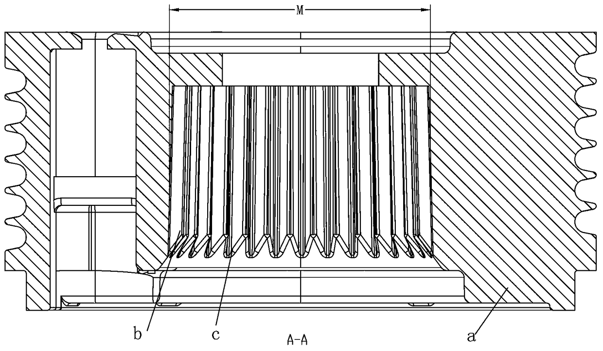
technical field [0001] The invention relates to the technical field of detection equipment, in particular to an instrument for measuring the inner diameter of a tooth groove of an internal gear. Background technique [0002] In order to ensure the quality of the internal gear, the internal gear needs to be measured before leaving the factory to eliminate unqualified products. The detection items include the inner diameter M of the tooth groove. [0003] Such as figure 1 with figure 2 As shown, the inner wall of the internal gear a is provided with a ring of teeth b, and a tooth groove c is provided between the two teeth. When measuring the existing inner diameter micrometer, the two probes need to be inserted into the two coggles c on the same diameter, and then the distance between the two coggles c, that is, the length of the inner diameter M of the cogging, can be obtained by reading. [0004] This method has the following disadvantages: 1. When the measuring personn...

Claims


Application Information

Patent Timeline
Patent Type & Authority Applications(China)
IPC IPC(8): G01B5/12
CPCG01B5/12
Inventor 刘勇王自昌
Owner DONGGUAN TIANLONG AKEDA ELECTRONICS CO LTD
Learn More