Safety mechanical fault diagnosis detection device

A technology for mechanical faults and detection devices, applied in measuring devices, instruments, etc., can solve the problems of difficult diagnosis of mechanical faults, difficult mechanical faults, and single data collection, and achieve the effect of convenient operation, improved accuracy, and avoid affecting detection.

Inactive Publication Date: 2018-12-14
佛山市北科科技创新服务中心
View PDF0 Cites 2 Cited by
  • Summary
  • Abstract
  • Description
  • Claims
  • Application Information

AI Technical Summary

Problems solved by technology

Existing mechanical faults are difficult to accurately diagnose, data collection is single, external water vapor and other factors affect the detection results during detection, and it is difficult to accurately judge mechanical faults

Method used


Image

  • Safety mechanical fault diagnosis detection device
  • Safety mechanical fault diagnosis detection device
  • Safety mechanical fault diagnosis detection device

Examples


Embodiment 1

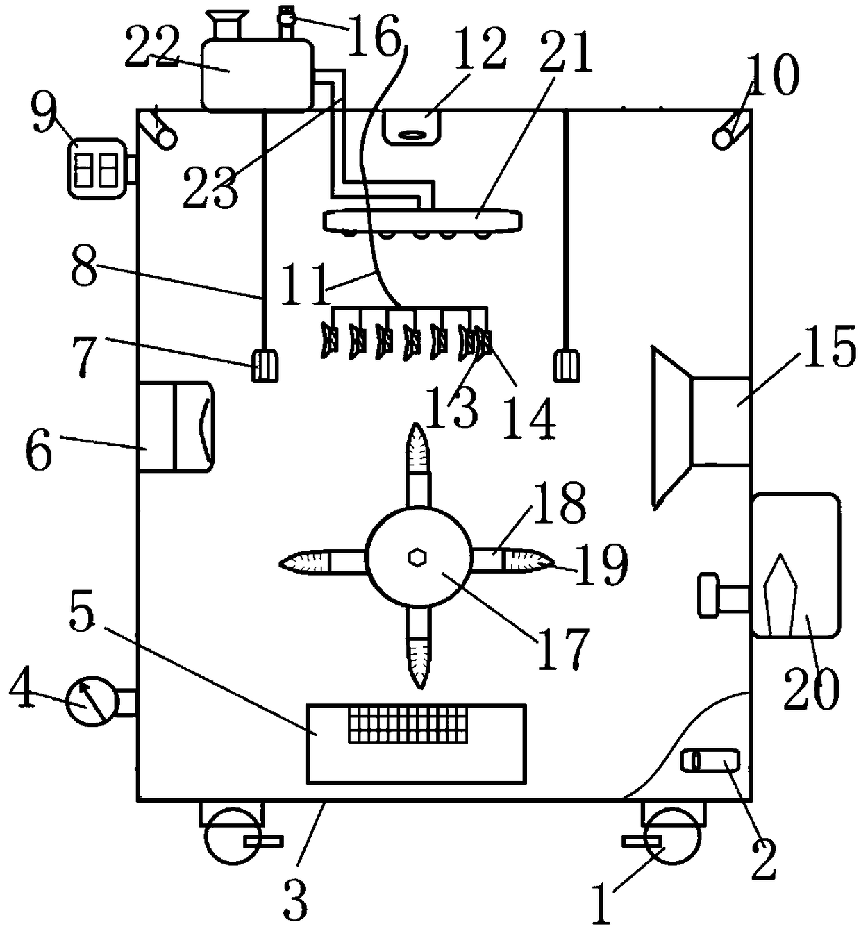
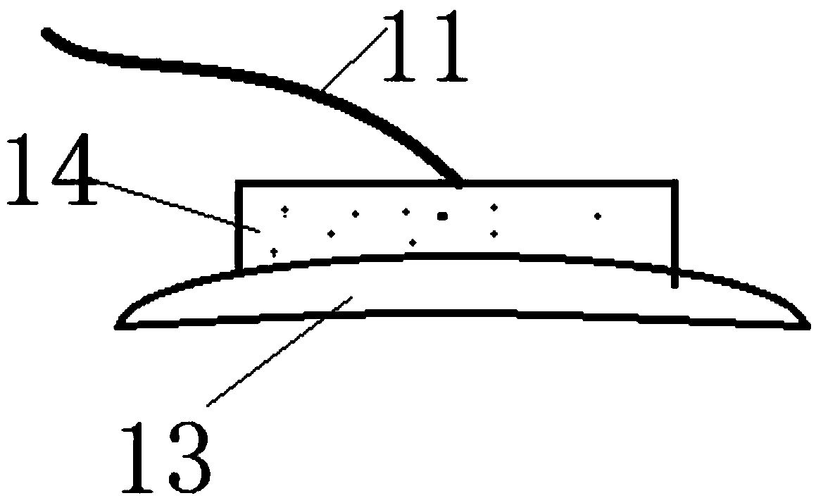
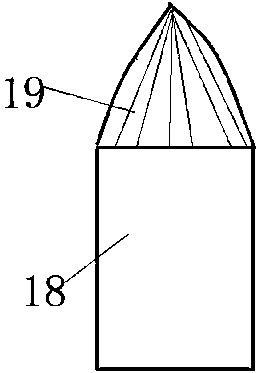
[0018] Example 1: Please refer to Figure 1-3 , a safety mechanical fault diagnosis and detection device, including a guide wheel 1, a box body 3, a thermometer 4, a heater 5, an infrared detector 6, a fixing clip 7, a timer 9, an LED light 10, a data transmission line 11, a camera 12, Temperature sensor 14 and ultrasonic detector 15, described casing 3 is provided with sealed box door, opens the sealed box door and puts in the machinery to be detected, and box body 3 inner wall is provided with heater 5, and box body 3 side walls are provided with Thermometer 4, the thermometer 4 controls and records the heating temperature of the heater 5, the inner wall of the box body 3 is also provided with an infrared detector 6 and an ultrasonic detector 15, the top of the box body 3 is provided with an elastic rope 8, and the elastic rope 8 is provided with a fixing clip 7. The object to be tested is fixed and clamped by the fixing clip 7. The data transmission line 11 is provided in t...

Embodiment 2

[0021] Embodiment 2: On the basis of Embodiment 1, a guide wheel 1 is provided on the bottom surface of the box body 3, and a hand brake is provided on the guide wheel 1. The guide wheel 1 is convenient for the device to move, saving time and effort, and a level is provided on the side wall of the bottom end of the box body 3 2. The spirit level 2 ensures the level of the device when it is placed to avoid affecting the detection. The box body 3 is provided with a timer 9, which controls and records the detection time. The inner wall of the top of the box body 3 is provided with an LED light 10 and a camera 12. The camera 12 and The remote display device is connected, and the detection situation in the box body 3 can be clearly seen through the camera 12, which is convenient for timely adjustment, and the LED lamp 10 provides illumination for convenient detection.

[0022] The working principle of the present invention is: the guide wheel of the present invention facilitates the...


PUM


Abstract

The invention discloses a safety mechanical fault diagnosis detection device. The safety mechanical fault diagnosis detection device comprises guide wheels, a box body, a heater, an infrared detector,fixed clamps, LED lamps, a camera, temperature sensors and an ultrasonic detector, wherein the guide wheels are arranged on the bottom surface of the box body; the heater is arranged on the inner wall of the box body; the infrared detector and the ultrasonic detector are further arranged on the inner wall of the box body; elastic ropes are arranged at the top end of the box body; the fixed clampsare arranged on the corresponding elastic ropes; a data transmission line is arranged in the box body, and a plurality of groups of temperature sensors are arranged on the data transmission line; a sucker is arranged on the surface of each temperature sensor; a gas filling tank is arranged on the side wall of the box body; a liquid water storage tank is arranged on the box body, and a rotating wheel is arranged in the box body; blades are uniformly arranged on the outer wall of the rotating wheel; a brush is arranged at the outer end head of each blade; and the LED lamps and the camera are arranged on the inner wall of the top end of the box body. By virtue of the device, multiple groups of different data are obtained and compared, the fault of the machine is accurately diagnosed, the influence of external factors to the detection result is reduced, and the accuracy is improved; and meanwhile, the structure is simple, the operation is convenient, and the popularization is facilitated.

Description

technical field [0001] The invention relates to a mechanical detection device, in particular to a safe mechanical fault diagnosis and detection device. Background technique [0002] Mechanical fault diagnosis is a technology that understands and masters the state of the machine during operation, determines its overall or partial normal or abnormality, detects faults and their causes early, and can predict the development trend of faults. Oil monitoring, vibration monitoring, noise monitoring, performance trend analysis and non-destructive testing are the main diagnostic techniques. With the development of computer technology, embedded technology and emerging virtual instrument technology, fault diagnosis devices and instruments have developed from the original analog monitoring instrument to the current computer-based real-time online monitoring - fault diagnosis system and portable computer-based Monitoring and analysis system. This type of system generally has powerful s...

Claims


Application Information

Patent Timeline
Patent Type & Authority Applications(China)
IPC IPC(8): G01D21/02
CPCG01D21/02
Inventor 黄海
Owner 佛山市北科科技创新服务中心
Why Eureka
Try Eureka