Simulation optimization method of compressor piping vibration of constant frequency air conditioner

An optimization method and compressor technology, applied in design optimization/simulation, instruments, special data processing applications, etc., can solve problems such as ambiguity in the optimization direction of the compressor piping system, and achieve the effect of shortening the design cycle

Inactive Publication Date: 2018-12-14
四川长虹空调有限公司
View PDF5 Cites 12 Cited by
  • Summary
  • Abstract
  • Description
  • Claims
  • Application Information

AI Technical Summary

Problems solved by technology

[0003] The technical problem to be solved by the present invention is: to overcome the problem that the optimization direction of the existing compressor p

Method used


Image

  • Simulation optimization method of compressor piping vibration of constant frequency air conditioner
  • Simulation optimization method of compressor piping vibration of constant frequency air conditioner
  • Simulation optimization method of compressor piping vibration of constant frequency air conditioner

Examples


Embodiment 1

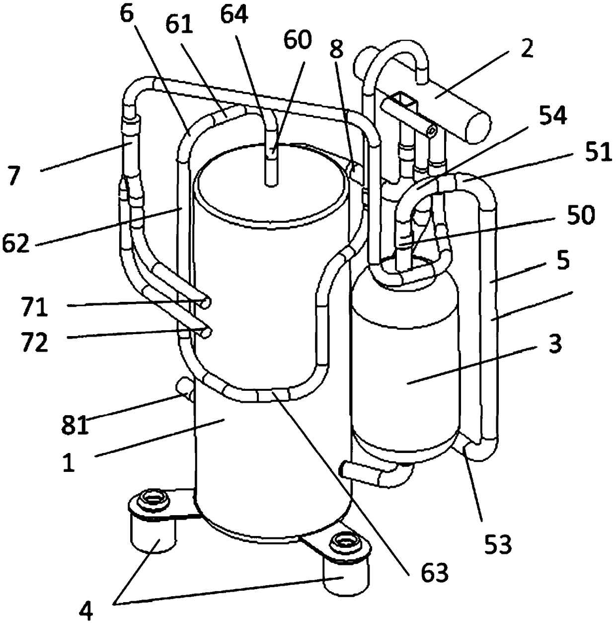
[0058] Such as figure 2 As shown, the finite element model may include a compressor cylinder 1, a four-way valve 2, a liquid storage tank 3 connected to the compressor cylinder 1, a rubber foot 4 for fixing the compressor cylinder 1, and a suction pipe connected to the liquid storage tank 3. The air port and the suction pipe 5 of the four-way valve 2, the exhaust pipe 6 connecting the exhaust port of the compressor cylinder 1 and the four-way valve 2, and the connecting pipe 7 for connecting the four-way valve 2 and the heat exchanger And the connecting pipe two 8 for connecting the four-way valve 2 and the shut-off valve, the connecting pipe one 7 includes the boundary nozzle one 71 and the boundary nozzle two 72, and the connecting pipe two 8 includes the boundary nozzle three 81.

[0059] The suction pipe 5 includes a first extension portion 50 of the suction pipe extending outward from the suction port of the liquid storage tank 3, a first bent portion 51 of the suction p...

Embodiment 2

[0071] The difference between this embodiment and the first embodiment is that there is only one stress peak value on the stress frequency response curves of the observation point 1 and the observation point 2 respectively.

[0072] Such as Figure 7 As shown, the finite element model may include a compressor cylinder 1, a four-way valve 2, a liquid storage tank 3 connected to the compressor cylinder 1, a rubber foot 4 for fixing the compressor cylinder 1, and a suction pipe connected to the liquid storage tank 3. The air port and the suction pipe 5 of the four-way valve 2, the exhaust pipe 6 connecting the exhaust port of the compressor cylinder 1 and the four-way valve 2, and the connecting pipe 7 for connecting the four-way valve 2 and the heat exchanger And the connecting pipe two 8 for connecting the four-way valve 2 and the shut-off valve, the connecting pipe one 7 includes the boundary nozzle one 71 and the boundary nozzle two 72, and the connecting pipe two 8 includes ...


PUM


Abstract

The invention relates to the field of finite element simulation. For solving the problem that the optimization direction of the existing compressor piping system is not clear, the invention presents asimulation optimization method of compressor piping vibration of a constant frequency air conditioner. The method comprises the steps of performing modal analysis and harmonic response analysis fora finite element model, determining the peak frequency corresponding to the stress peak in the stress frequency response curve; judging whether the result of harmonic response analysis accords with the evaluation standard of pipe harmonic response analysis; if yes, trial-manufacturing the compressor piping, otherwise, selecting the peak frequency with the smallest absolute value difference from the working frequency of the compressor and recording the same as the peak frequency one, selecting the natural frequency with the smallest absolute difference between the peak frequency and the naturalfrequency and obtaining the natural vibration mode corresponding to the natural frequency and denoting the same as the natural vibration mode one; according to the natural vibration mode to determinethe part of the finite element model with the largest vibration amplitude and the vibration direction of the part, adjusting the mass of the part and/or adjusting the stiffness of the part in the vibration direction. The invention is suitable for optimizing the piping system of the compressor.

Description

technical field [0001] The invention relates to the field of finite element simulation, in particular to a method for simulating the vibration of a compressor pipe of a fixed-frequency air conditioner and optimizing the simulation result. Background technique [0002] In the air conditioner, the compressor is the "heart" and the source of excitation, and the piping is the direct part connecting the compressor and the heat exchange system of the air conditioner, so the vibration of the piping is relatively large. For the evaluation of piping vibration of fixed-frequency air conditioners, there are many evaluation methods in the industry, such as evaluating the piping scheme through simulation first, and then further evaluating the piping scheme through experimental testing. Among them, the simulation evaluation is to evaluate the advantages and disadvantages of the piping scheme in the conceptual design stage by means of simulation. For example, the Chinese patent application...

Claims


Application Information

Patent Timeline
IPC IPC(8): G06F17/50
CPCG06F30/23
Inventor 李磊鑫李越峰董维邱名友
Owner 四川长虹空调有限公司
Why Eureka
Try Eureka