Planting cutting device
A cutting and equipment technology, applied in the field of cutting equipment for planting, can solve the problems of irregularity, laborious transplanting method, low cutting planting efficiency, etc., and achieve the effect of improving efficiency and facilitating cutting
- Summary
- Abstract
- Description
- Claims
- Application Information
AI Technical Summary
Problems solved by technology
Method used
Image
Examples
Embodiment 1
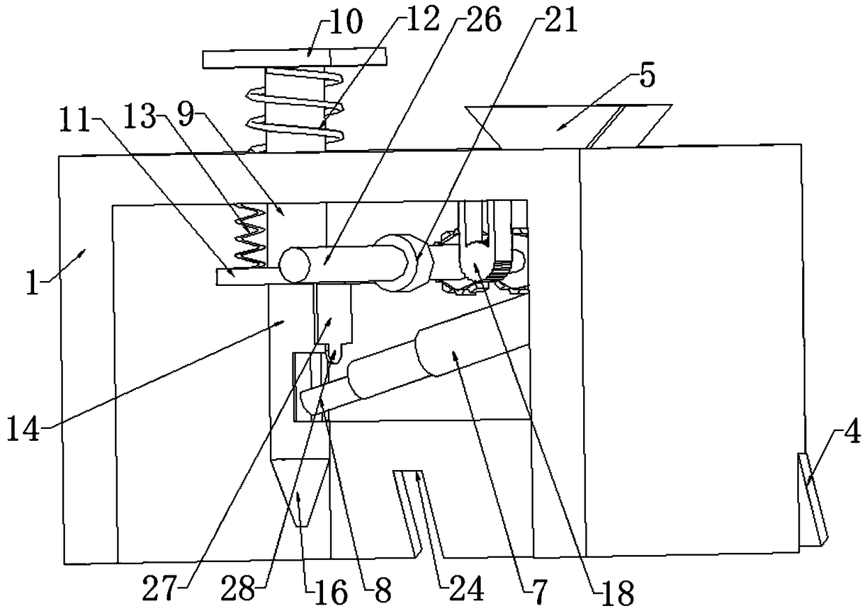
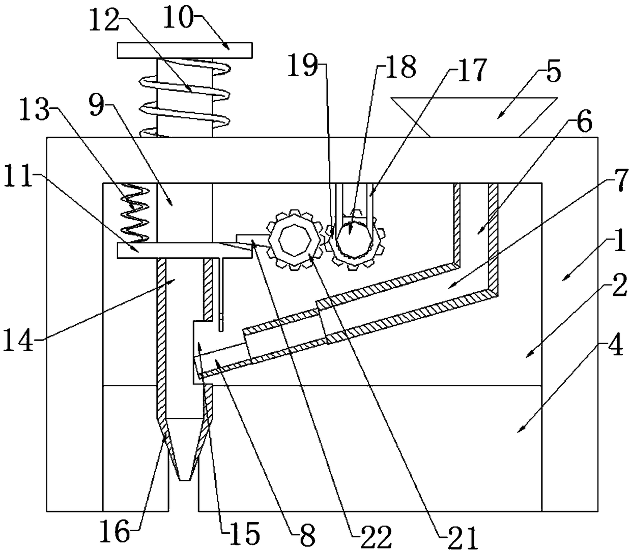
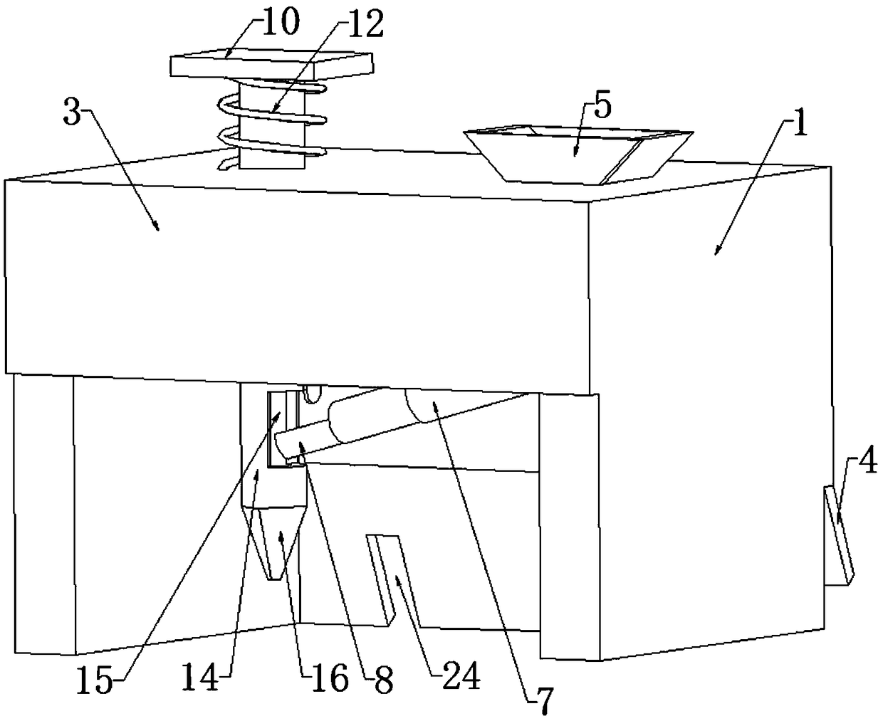
[0036] refer to figure 1 , figure 2 , image 3 , Figure 4 , a cutting device for planting, comprising a fixed plate 1, the fixed plate 1 is a U-shaped structure, the side walls of the fixed plate 1 are respectively fixedly connected with a first baffle plate 2 and a second baffle plate 3, and the top of the fixed plate 1 is fixedly connected with a throwing plate The hopper 5 is provided with a round hole in the feeding hopper 5, and a feeding mechanism is connected to the round hole. An opening is provided on the fixed plate 1, and a vertically arranged sliding rod 9 is slidably connected in the opening, and the bottom of the sliding rod 9 is fixed. A third conveying pipe 14 is connected, and the end of the third conveying pipe 14 away from the sliding rod 9 is fixedly connected with a conical head 16, and the end of the sliding rod 9 away from the third conveying pipe 14 extends upward through the fixed plate 1, and the extension end is connected with a The first pressu...
Embodiment 2
[0040] refer to figure 1 , figure 2 , Figure 5 , Figure 6 , a kind of cutting equipment for planting, which is basically the same as that of Embodiment 1, furthermore, the inner wall of the top of the fixed plate 1 is fixedly connected with a support plate 17, the cutting adjustment assembly includes a motor 18, and the motor 18 is fixedly connected with the support plate 17, and supports The end of the plate 17 away from the fixed plate 1 is fixedly connected with a motor 18, and the output end of the motor 18 is fixedly connected with a first rotating shaft 25, and the end of the first rotating shaft 25 away from the motor 18 is rotatably connected to the inner wall of the first baffle plate 2. The outer wall of the rotating shaft 25 is fixedly connected with the first gear 19; through the rotation of the motor 18 on the support plate 17, the first rotating shaft 25 is rotated by the motor 18, and the first rotating shaft 25 will drive the first gear 19 to rotate, there...
Embodiment 3
[0043] refer to figure 1 , figure 2 , image 3 , Figure 4 , Figure 6 , refer to figure 1 , figure 2 , image 3 , Figure 4 , a cutting device for planting, comprising a fixed plate 1, the fixed plate 1 is a U-shaped structure, the side walls of the fixed plate 1 are respectively fixedly connected with a first baffle plate 2 and a second baffle plate 3, and the top of the fixed plate 1 is fixedly connected with a throwing plate The hopper 5 is provided with a round hole in the feeding hopper 5, and a feeding mechanism is connected to the round hole. An opening is provided on the fixed plate 1, and a vertically arranged sliding rod 9 is slidably connected in the opening, and the bottom of the sliding rod 9 is fixed. A third conveying pipe 14 is connected, and the end of the third conveying pipe 14 away from the sliding rod 9 is fixedly connected with a conical head 16, and the end of the sliding rod 9 away from the third conveying pipe 14 extends upward through the fi...
PUM
 Abstract
Description
Claims
Application Information
 - R&D
- Intellectual Property
- Life Sciences
- Materials
- Tech Scout
- Unparalleled Data Quality
- Higher Quality Content
- 60% Fewer Hallucinations
Browse by: Latest US Patents, China's latest patents, Technical Efficacy Thesaurus, Application Domain, Technology Topic, Popular Technical Reports.
© 2025 PatSnap. All rights reserved.Legal|Privacy policy|Modern Slavery Act Transparency Statement|Sitemap|About US| Contact US: help@patsnap.com


