High-efficiency automatic sand making machine

A sand making machine and high-efficiency technology, applied in grain processing and other directions, can solve the problems of inability to independently crush sand and poor automation, and achieve the effect of high automation and high crushing efficiency.

Inactive Publication Date: 2018-12-18
ZAOZHUANG SNKSAN INTELLIGENT MACHINERY CO LTD
View PDF0 Cites 0 Cited by
  • Summary
  • Abstract
  • Description
  • Claims
  • Application Information

AI Technical Summary

Problems solved by technology

[0004] However, the traditional sand making machine can only crush the sand once or more times, and cannot independently crush the sand according to the particle size of the required sand, and the degree of automation is not good.

Method used


Image

  • High-efficiency automatic sand making machine
  • High-efficiency automatic sand making machine
  • High-efficiency automatic sand making machine

Examples


Embodiment 1

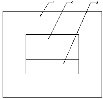
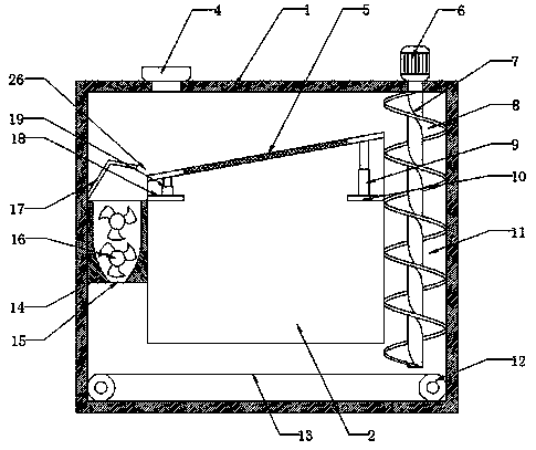
[0028] see Figure 1-4 , this embodiment provides a high-efficiency automatic sand making machine, including a crushing box 1 and a fine sand storage box 2; the fine sand storage box 2 is arranged in the middle of the crushing box 1, and the right side of the fine sand storage box 2 is connected A lifting channel 11 is arranged between the crushing boxes 1; a lifting shaft 7 is arranged in the lifting channel 11; a spiral lifting plate 8 is fixedly connected to the lifting shaft 7, and the top of the lifting shaft 7 passes through the crushing box The body 1 is fixedly connected with the lifting motor 6; the lower end of the spiral lifting plate 8 is provided with a horizontally arranged conveyor belt 13 driven by the feeding roller 12, the lifting motor 6 is started, and the lifting motor 6 drives the lifting shaft 7 Rotating, the lifting rotating shaft 7 drives the spiral lifting material plate 8 to rotate, and the lower stone is lifted upward through the spiral lifting mate...

Embodiment 2

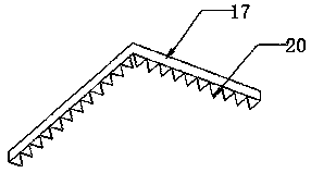
[0031] see figure 2 with Figure 5 , a high-efficiency automatic sand making machine, also includes a first shock absorbing mechanism 9 and a second shock absorbing mechanism 19; the first shock absorbing mechanism 9 is arranged under the solid plate on the right side of the screen plate 5, and the second shock absorbing mechanism 19 is arranged below the solid plate on the left side of the sieve plate 5; the internal structure of the first shock absorbing mechanism 9 and the second shock absorbing mechanism 19 is the same, and the lower end of the first shock absorbing mechanism 9 is fixedly connected to the first fixed plate 10, and the second shock absorbing mechanism The lower end of the shock mechanism 19 is fixedly connected to the second fixed plate 18;

[0032] The first damping mechanism 9 includes a damping sleeve 22 and a movable rod 21; the movable rod 21 is inserted into the interior of the damping sleeve 22 from the top of the damping sleeve 22, and the bottom ...


PUM


Abstract

The invention provides a high-efficiency automatic sand making machine, and belongs to the technical field of sand making machines. The high-efficiency automatic sand making machine comprises a crushing box body and a fine sand storage box, wherein the fine sand storage box is arranged in the middle of the crushing box body. A material lifting channel is formed between the right side of the fine sand storage box and the crushing box body, a material lifting rotating shaft is arranged in the material lifting channel, a spiral material lifting plate is fixedly connected to the material lifting rotating shaft, the top of the material lifting rotating shaft passes through the crushing box body and is fixedly connected with a material lifting motor, and a horizontally arranged conveying belt driven by a conveying roller is arranged at the lower end of the spiral material lifting plate. According to the high-efficiency automatic sand making machine, a feeding inlet is formed in the top wallof the crushing box body directly above a solid plate on the left side of a sieve plate, stones thrown in from the feeding inlet hit the solid plate on the left side of the sieve plate, a first damping mechanism and a second damping mechanism are matched to enable the sieve plate to vibrate up and down to play a role of vibrating and sieving materials, smooth sieving of fine sand can be completedwithout additionally arranging an exciting device, and high efficiency and energy saving are realized; and sand and stone raw materials can be recycled and crushed by setting the material lifting channel, and the automation degree is high.

Description

technical field [0001] The invention relates to a sand making machine, in particular to a high-efficiency automatic sand making machine. Background technique [0002] With the acceleration of economic construction and social development, the demand for sand is also increasing, and the phenomenon of random mining and excavation of river sand continues to appear, and measures to prohibit mining and excavation have been adopted in various places. Therefore, artificial sand making machines should be used And born. [0003] In the field of mining equipment, the application of sand making machines is very common. The working principle of commonly used sand making machines is to throw rock materials into the sand making machine. After entering the sand making machine, the rock materials are divided into middle throwing materials and surrounding For blanking, the spindle group of the sand making machine drives the rotor group to rotate at a high speed, and the rotor group hits the ...

Claims


Application Information

Patent Timeline
Patent Type & Authority Applications(China)
IPC IPC(8): B02C19/00B02C23/00B02C23/12
CPCB02C19/00B02C23/00B02C23/12
Inventor 孙法虎孙启祥马驰
Owner ZAOZHUANG SNKSAN INTELLIGENT MACHINERY CO LTD
Why Eureka
Try Eureka