Extrusion casting device

A squeeze casting and connecting device technology, which is applied in the field of casting modeling, can solve problems such as mold damage and casting object damage, and achieve the effect of convenient mutual combination and separation, and avoiding damage

Active Publication Date: 2018-12-18
MAANSHAN XINGLONG FOUNDRY CO LTD
View PDF13 Cites 0 Cited by
  • Summary
  • Abstract
  • Description
  • Claims
  • Application Information

AI Technical Summary

Problems solved by technology

[0003] When extrusion casting an object, it is necessary to protect the casting mold, bec

Method used


Image

  • Extrusion casting device
  • Extrusion casting device
  • Extrusion casting device

Examples


Embodiment 1

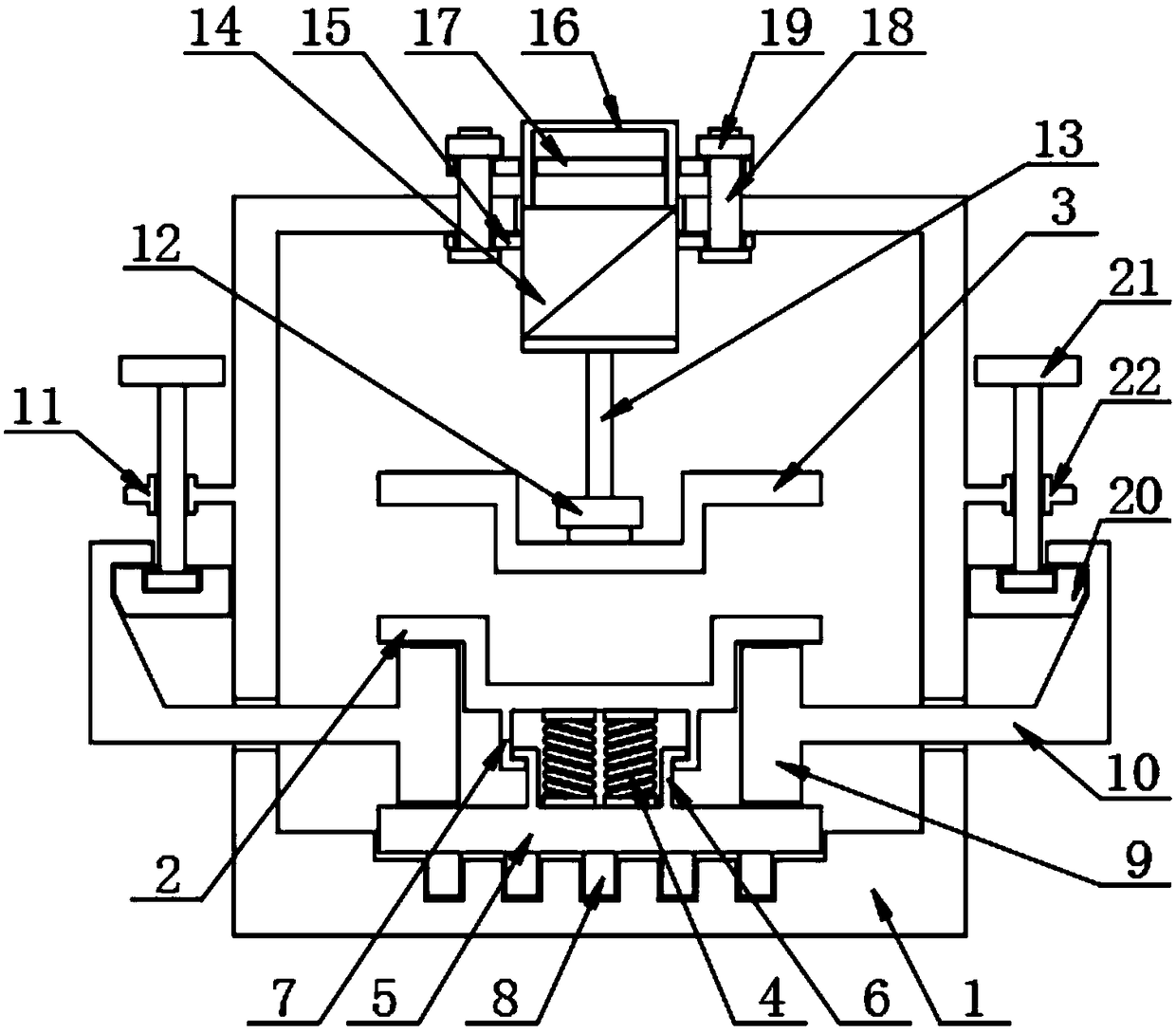
[0024] The present invention provides such as Figure 1-4 A squeeze casting device shown includes a bracket 1, a lower mold 2 is arranged inside the bracket 1, an upper mold 3 is arranged on the top of the lower mold 2, and a first spring 4 is arranged on the bottom of the lower mold 2, The bottom of the first spring 4 is provided with a bottom plate 5, the outside of the first spring 4 is provided with a lower lever 6, the top of the lower lever 6 is provided with an upper lever 7, and the bottom of the bottom plate 5 is provided with a protruding lever 8 , both sides of the top of the bottom plate 5 are provided with support blocks 9, one side of the support block 9 is provided with a pull frame 10, the inner side of the pull frame 10 is provided with a moving device 11, and the top of the upper mold 3 is provided with a connecting device 12, The top of the connecting device 12 is provided with a telescopic rod 13, the top of the telescopic rod 13 is provided with a cylinder...

Embodiment 2

[0027] The moving device 11 includes a moving block 20, the top of the moving block 20 is provided with a rotating rod 21, and the outside of the support 1 is provided with a support plate 22, and the rotating rod 21 is matched with the pull frame 10 through the moving block 20, and rotates Rod 21, and then rotating rod 21 drives moving block 20 to move down through support plate 22, and moving block 20 pulls support block 9 to break away from lower mold 2 through pull frame 10, reaches the decompression effect to lower mold 2.

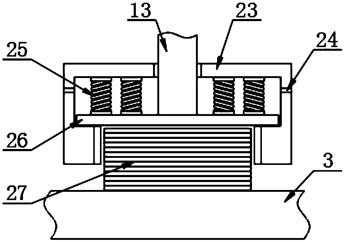
[0028] The connecting device 12 includes a rotary sleeve 23, the outer surface of the rotary sleeve 23 is provided with an oil hole 24, the inner side of the rotary sleeve 23 is provided with a second spring 25, and the bottom of the second spring 25 is provided with a pressing plate 26. The top surface of the upper die 3 is provided with a screw block 27, and the rotary sleeve 23 is threadedly connected with the screw block 27, and the rotary sleeve 2...


PUM


Abstract

The invention discloses an extrusion casting device. The extrusion casting device comprises a support. A lower die is arranged on the inner side of the support. An upper die is arranged on the top ofthe lower die. First springs are arranged at the bottom of the lower die. A bottom plate is arranged at the bottoms of the first springs. Lower clamping rods are arranged on the outer sides of the first springs. Upper clamping rods are arranged on the tops of the lower clamping rods. Protruding rods are arranged at the bottom of the bottom plate. Support blocks are arranged on the two sides of thetop of the bottom plate. Pull frames are arranged on one sides of the support blocks. Moving devices are arranged on the inner sides of the pull frames. A connecting device is arranged on the top ofthe upper die. A telescopic rod is arranged on the top of the connecting device. Through the arrangement of the moving devices, an air cylinder works and drives the telescopic rod and the upper die tomove downwards, accordingly, the upper die and the lower die achieve the object extrusion effect, and after extrusion is complete, rotation rods are rotated and then drive movable blocks to move downwards through support plates, the movable blocks pull the support blocks to disengage from the lower die through the pull frames, the lower die pressure reduction effect is achieved, accordingly, thelower die is protected, and lower die damage is avoided.

Description

technical field [0001] The invention relates to the technical field of casting molding, in particular to a squeeze casting device. Background technique [0002] Squeeze casting, also known as liquid die forging, is to inject molten metal or semi-solid alloy directly into the open mold, and then close the mold to generate filling flow to reach the outer shape of the workpiece, and then apply high pressure to make the solidified The metal (shell) undergoes plastic deformation, the unsolidified metal is subjected to isostatic pressure, and high-pressure solidification occurs at the same time, and finally the method of obtaining the workpiece or blank. [0003] When extrusion casting an object, it is necessary to protect the casting mold, because excessive pressure will cause damage to the mold, thereby damaging the casting object. [0004] Therefore, it is necessary to invent a squeeze casting device to solve the above problems. Contents of the invention [0005] The object...

Claims


Application Information

Patent Timeline
IPC IPC(8): B22D18/02
CPCB22D18/02
Inventor 张家俊
Owner MAANSHAN XINGLONG FOUNDRY CO LTD
Why Eureka
Try Eureka