Screw locking mechanism

A locking mechanism and screw technology, applied in metal processing, metal processing equipment, manufacturing tools, etc., can solve the problems of high labor intensity, high labor cost, difficulty in ensuring quality consistency, etc., and improve processing accuracy and efficiency. The effect of saving working hours

Pending Publication Date: 2018-12-18
深圳市山龙智控有限公司
View PDF0 Cites 5 Cited by
  • Summary
  • Abstract
  • Description
  • Claims
  • Application Information

AI Technical Summary

Problems solved by technology

[0002] As a commonly used fastener, screws are mainly used to connect two or more parts of the product. At present, the screw assembly of many products is mostly performed by workers holding a screwdriver to tighten the screws. In the mass production process, workers often The labor intensity is high, and the efficiency is low, the labor cost is high, and it is difficult to ensure the consistency of quality, so it is far from meeting the needs of the industry.
[0003] With the transformation and upgrading of my country's manufacturing industry au

Method used


Image

  • Screw locking mechanism
  • Screw locking mechanism
  • Screw locking mechanism

Examples


Embodiment Construction

[0024] In order to make those skilled in the art more clearly understand the purpose, technical solutions and advantages of the present invention, the present invention will be further described below in conjunction with the accompanying drawings and embodiments.

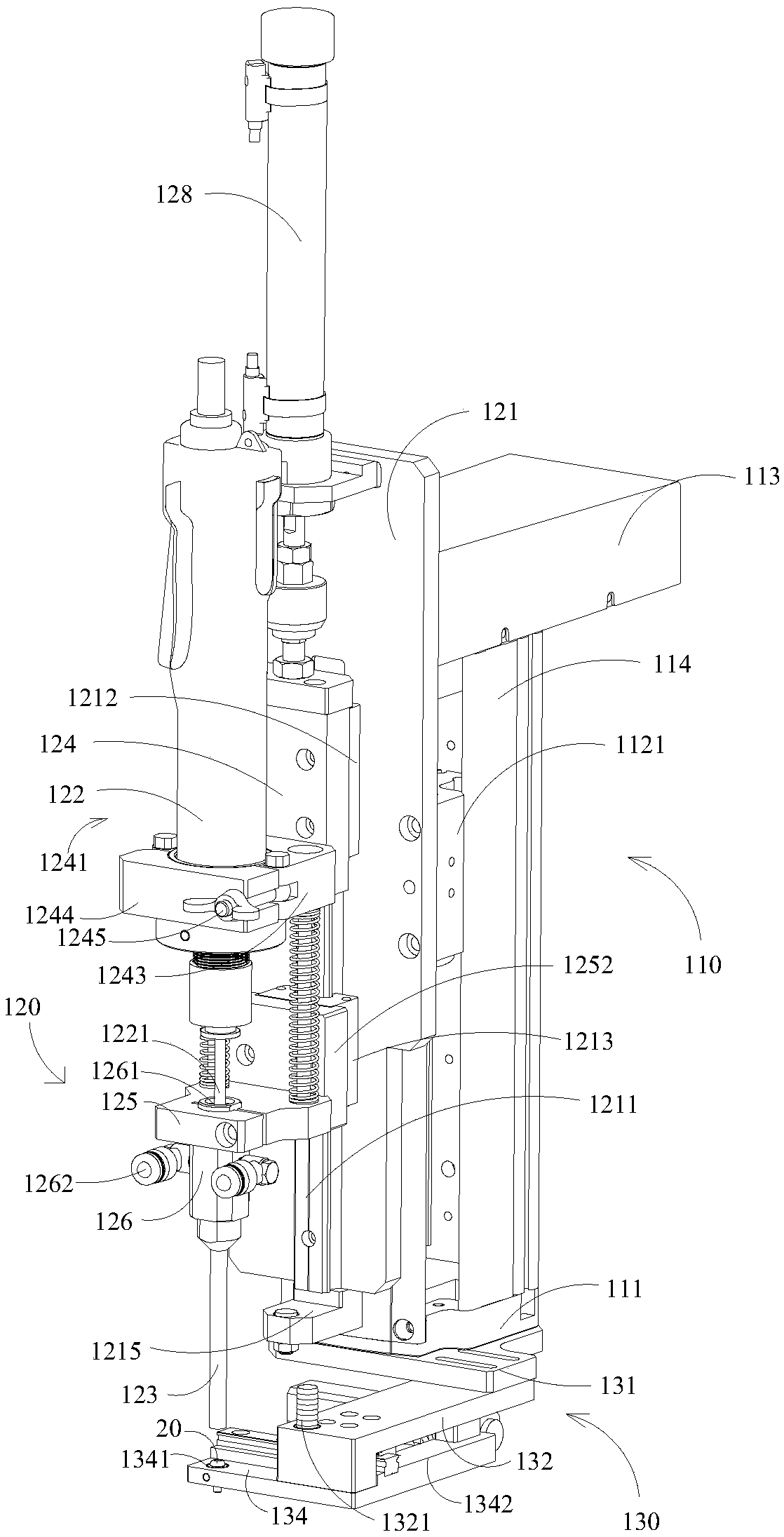
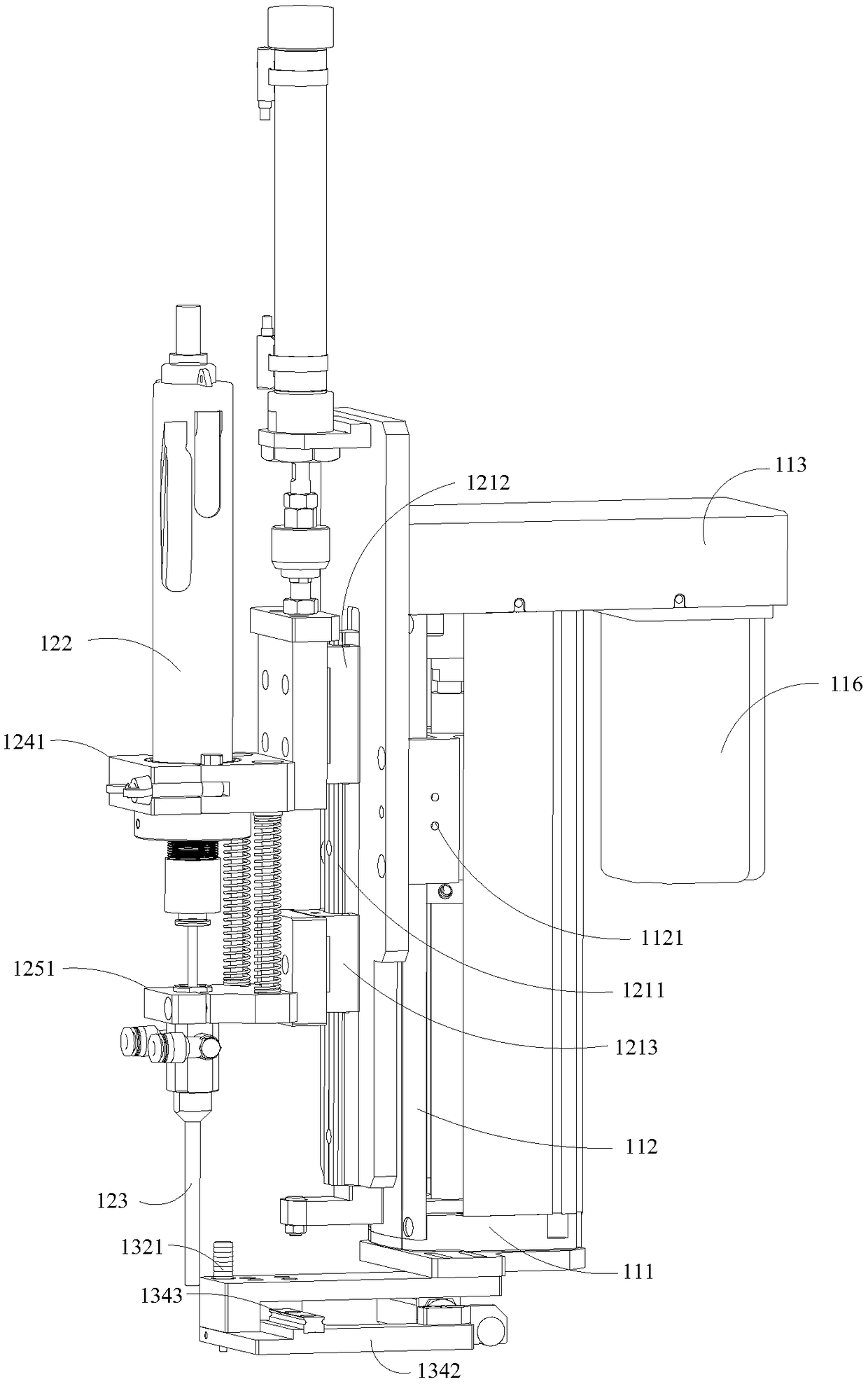
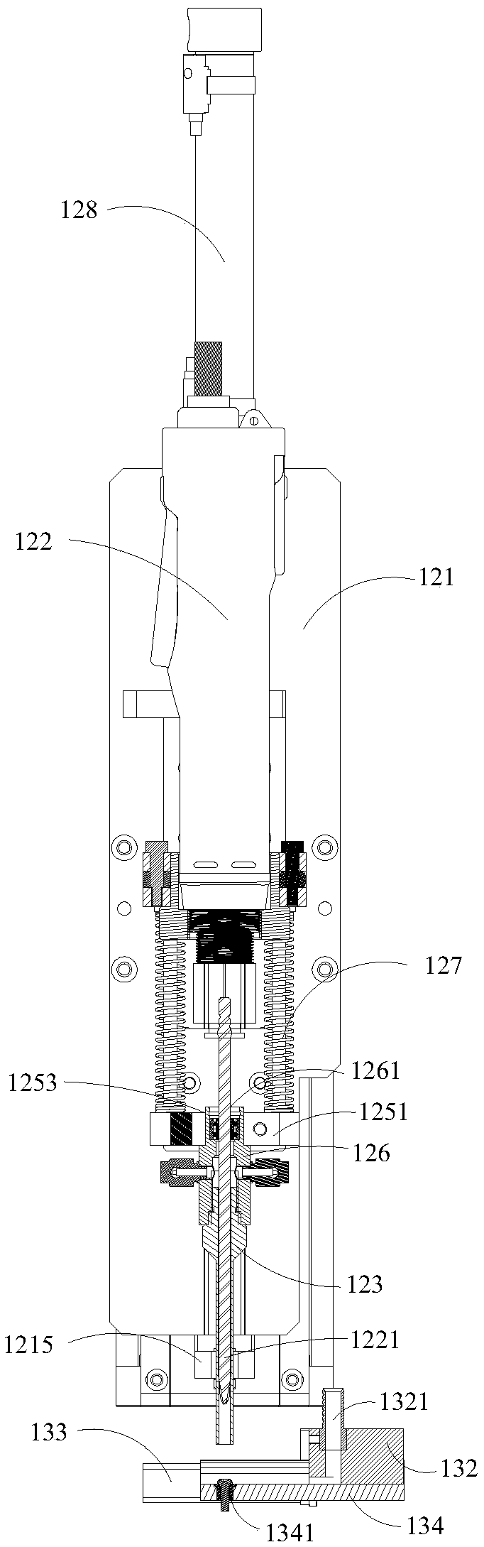
[0025] refer to Figure 1 to Figure 7 , in this embodiment, the screw locking mechanism includes a support module 110 , a locking module 120 and a screw feeding module 130 . Wherein, the support module 110 includes a support base 111 and a cover plate 112 , and the cover plate 112 is vertically arranged at one end of the support base 111 . The locking module 120 is arranged on one side of the supporting module 110, and includes a bottom plate 121, an electric batch 122 and a suction nozzle 123, and the bottom plate 121 is vertically arranged on one side of the supporting module 110 , the bottom plate 121 is installed on the cover plate 112, the electric batch mounting frame 124 and the suction nozzle mounting frame...


PUM


Abstract

The invention discloses a screw locking mechanism. The screw locking mechanism comprises a supporting module, a locking module and a screw feeding module. The supporting module comprises a supportingbase and a cover plate, wherein the cover plate is vertically arranged on the supporting base. The locking module comprises a base plate, an electric screwdriver and a suction nozzle, wherein the baseplate is vertically arranged on one side of the supporting module, and the electric screwdriver and the suction nozzle are arranged on the base plate through an electric screwdriver mounting frame and a suction nozzle mounting frame separately. The screw feeding module is arranged below the supporting module and comprises a supporting plate, a feed supporting plate, a cylinder and a screw supporting plate, wherein the other end of the feed supporting plate extends upwards to form a screw inlet pipe, a screw site used for receiving a screw conveyed from the screw inlet pipe is formed on the screw supporting plate, and a connecting plate connected with the tail end of a piston rod of the cylinder is formed at one end of the screw supporting plate so that the screw site of the screw supporting plate can move to a position below the suction nozzle. According to the screw locking mechanism, the screw feeding module capable of achieving automatic feeding is arranged, so that the locking precision and efficiency are improved.

Description

technical field [0001] The invention relates to the field of screw locking, in particular to a screw locking mechanism. Background technique [0002] As a commonly used fastener, screws are mainly used to connect two or more parts of the product. At present, the screw assembly of many products is mostly performed by workers holding a screwdriver to tighten the screws. In the mass production process, workers often The labor intensity is high, and the efficiency is low, the labor cost is high, and it is difficult to ensure the consistency of quality, so it is far from meeting the needs of the industry. [0003] With the transformation and upgrading of my country's manufacturing industry automation, a large number of suitable assembly robots are urgently needed in the manufacturing process to improve production efficiency and quality, and reduce production costs. Therefore, screw locking equipment has emerged to realize automatic screw locking and improve production efficiency....

Claims


Application Information

Patent Timeline
IPC IPC(8): B23P19/06
CPCB23P19/06
Inventor 李耀斌曾雨权凌波
Owner 深圳市山龙智控有限公司
Why Eureka
Try Eureka