

Clutch type electric bicycle chain wheel driving mechanism
A technology of electric bicycle and sprocket drive, which is applied in the direction of rider drive, vehicle parts, vehicle gearbox, etc. It can solve the problems of customer travel safety hazards, low flywheel service life, safety hazards, etc., to increase work stability and The effect of service life, reducing working hours and prolonging service life
- Summary
- Abstract
- Description
- Claims
- Application Information
AI Technical Summary
Problems solved by technology
Method used
Image

Examples
Embodiment 1
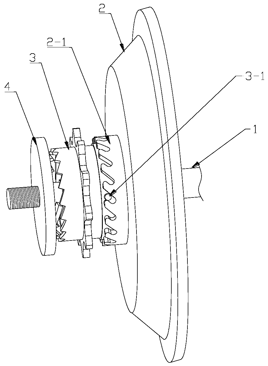
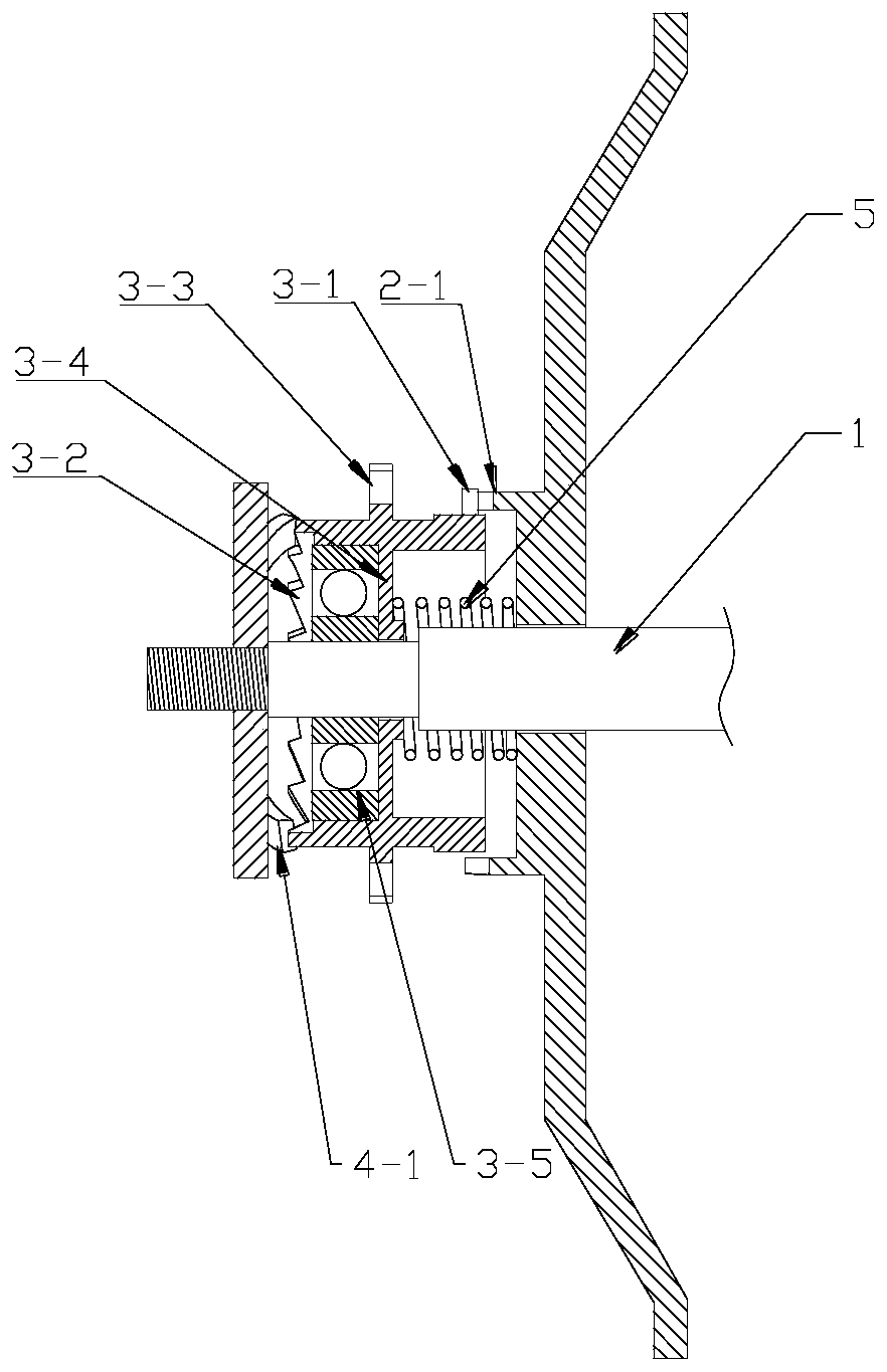
[0037] See attached Figure 1-2 , a clutch type electric bicycle sprocket drive mechanism, including a wheel shaft 1, a motor end plate 2, a sprocket 3, an outer end plate 4 and a return spring 5.
[0038] The motor end plate 2 is rotatably mounted on the wheel shaft 1, and a ring of teeth 2-1 is arranged on the outer end surface of the motor end plate.
[0039] The sprocket 3 is installed on the wheel shaft 1, and the sprocket 3 is located on the outside of the motor end plate 2. The sprocket 3 and the wheel shaft 1 are installed in rotation, and there is a gap sliding fit between the sprocket 3 and the wheel shaft 1. The sprocket Able to slide axially along the wheel shaft; on the opposite side of the sprocket 3 to the motor end plate 2, there is a locking column 3-1 that matches the teeth 2-1 of the motor end plate, and the locking column can be inserted into the motor end plate Between the teeth, the transmission engagement between the sprocket 3 and the motor end plate 2...
Embodiment 2
[0050] The operating method of the clutch type electric bicycle sprocket drive mechanism is as follows:
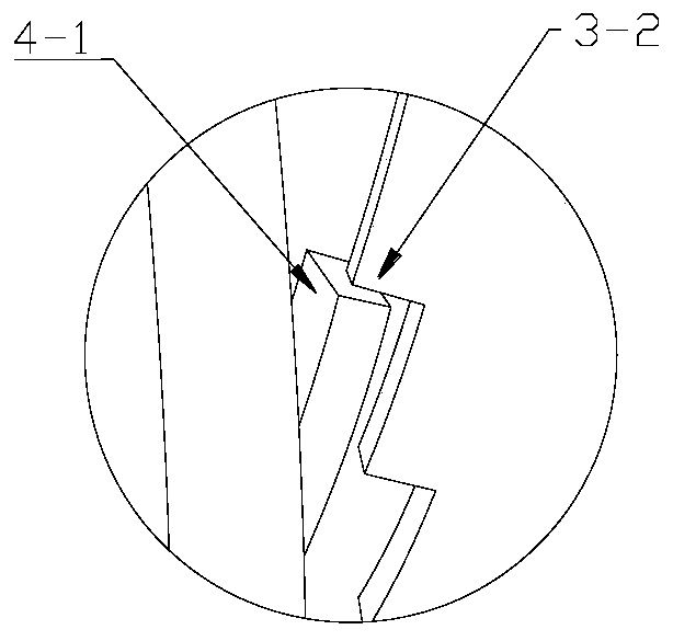
[0051]When the rider rides forward, the chain drives the sprocket to run forward, and when the sprocket runs forward, the pawl on the outer end plate will drive the sprocket to the motor end plate, so that the locking column on the sprocket enters the motor end Between the teeth of the disc, as the sprocket continues to run forward, the locking column enters the root of the tooth under the self-guiding action of the teeth, and at this time, the pawl and ratchet constraint is lost between the sprocket and the outer end disc (see attached Figure 5 ), does not affect the continued operation of the follow-up sprocket, and then the sprocket drives the entire motor wheel to run, and the car body moves forward.
[0052] When the rider stops riding, the sprocket moves to the outside under the action of the return spring and breaks away from the transmission engagement with the t...
PUM
 Abstract
Description
Claims
Application Information