Iron part and cutting chip separating device

A chip separation and parts technology, applied in metal processing machinery parts, maintenance and safety accessories, metal processing equipment, etc., can solve the problems of scratching the fingers of the staff, increasing the labor intensity of the staff, affecting the production efficiency, etc., to reduce the The effect of thread damage, smooth falling, and labor intensity reduction

Active Publication Date: 2018-12-18
安徽上禾阜机械配件有限公司
View PDF19 Cites 4 Cited by
  • Summary
  • Abstract
  • Description
  • Claims
  • Application Information

AI Technical Summary

Problems solved by technology

[0002] Machine tool is a kind of processing equipment widely used in mechanical processing. When lathe is processing the workpiece, it mainly uses the tool to cut the high-speed rotating workpiece to obtain the parts required in the production activities. Iron parts are daily It is a kind of part that is widely used in processing. When the lathe turns it, it will generate a lot of chips. When the turning is completed, the tool will cut the part, and the part will be mixed with the chips generated during turning. The existing The best way to deal with it is to manually pick the parts out of the chips, but this method will not only affect the production efficiency, but also increase the labor intensity of the staff, and some sharp chips may scratch the fingers of the staff

Method used


Image

  • Iron part and cutting chip separating device
  • Iron part and cutting chip separating device

Examples


Embodiment Construction

[0019] Through the description of the embodiments below, the specific implementation of the present invention includes the shape, structure, mutual position and connection relationship between the various parts, the function and working principle of each part, the manufacturing process and the operation and use method of the various components involved. etc., to make further detailed descriptions to help those skilled in the art have a more complete, accurate and in-depth understanding of the inventive concepts and technical solutions of the present invention.

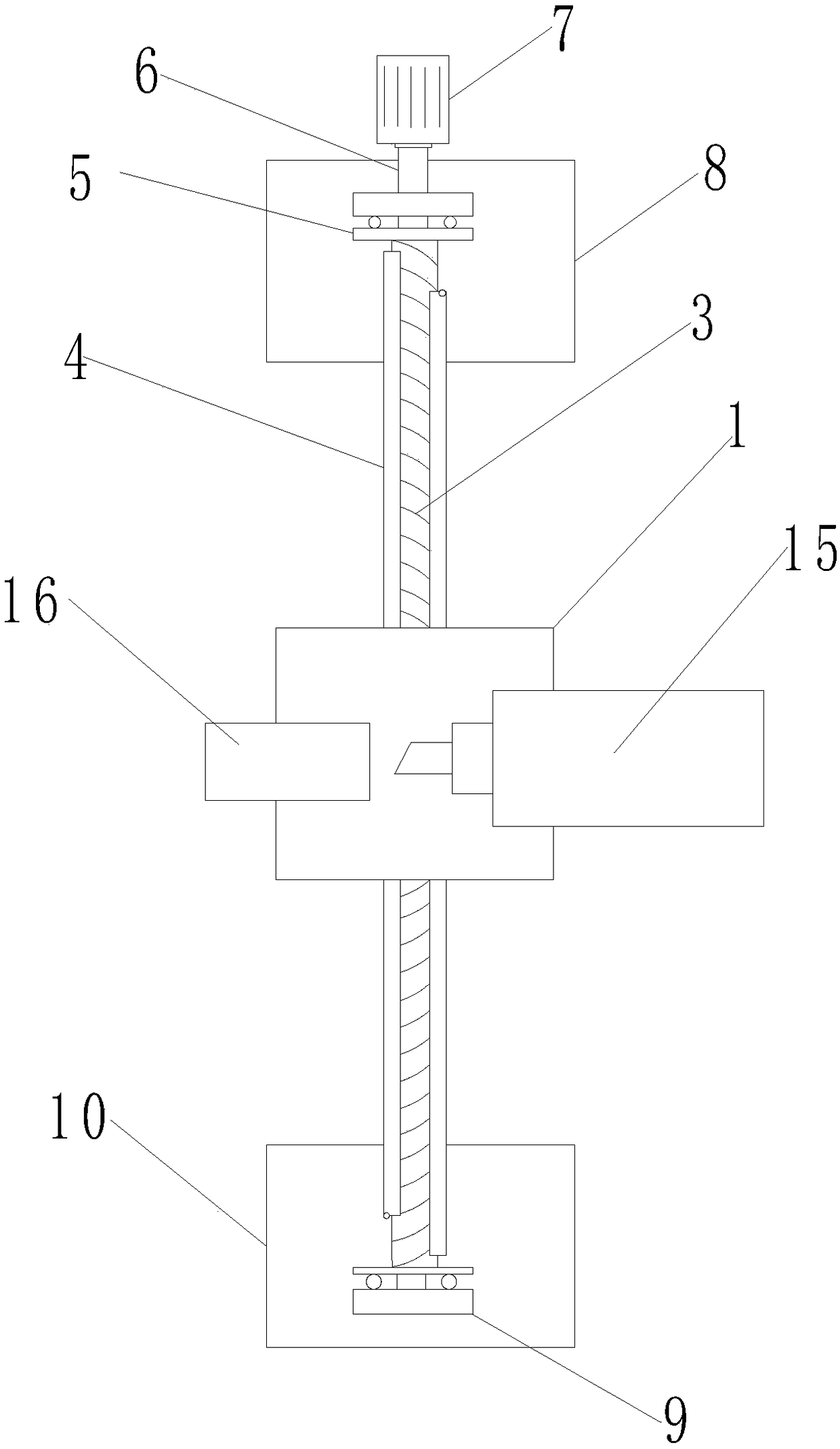
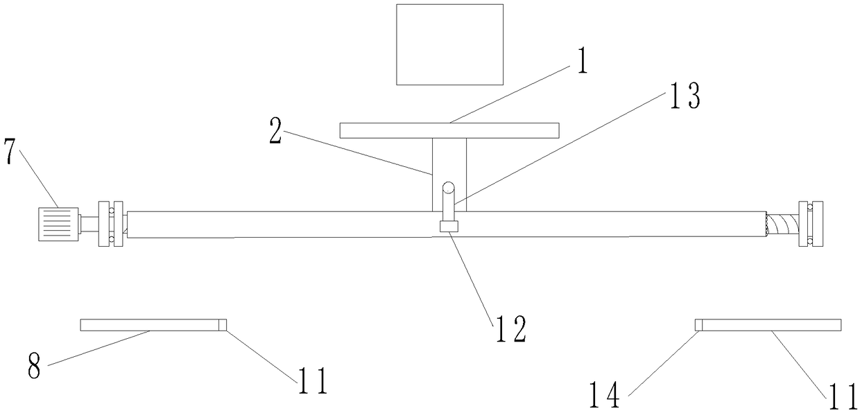
[0020] Such as Figure 1-2 As shown, this specific embodiment provides a device for separating iron parts and chips, including a magnetically controllable electromagnetic tray 1, the electromagnetic tray 1 is arranged below the turning position of the tool holder 15 and the workpiece 16, and the electromagnetic tray 1 is fixedly connected with a The screw nut part 2, the screw nut part 2 is connected with the screw rod...


PUM


Abstract

The invention provides an iron part and cutting chip separating device which comprises a magnetism-controllable electromagnetic tray. The initial position of the electromagnetic tray is arranged belowa turning position. The electromagnetic tray is fixedly connected with a screw nut part. The screw nut part is in connected with a screw rod in a threaded fit manner. The screw rod is fixedly installed in a guide rail and is driven by a motor. The motor can rotate forwards and backwards. A notch capable of making the screw nut part rotate by a certain angle is formed in each of the left end portion and the right end portion of the guide rail. A tray is arranged below each notch. The guide rail is further provided with an optical fiber sensor used for positioning the initial position. When aniron part is machined, cutting chips can be effectively separated from the part, the work efficiency is improved, the labor intensity of workers is lowered, meanwhile, impacts on a workpiece are further relieved, the precision of the workpiece is effectively protected, and the workpiece is prevented from being damaged.

Description

technical field [0001] The invention belongs to the technical field of lathe turning, and more specifically relates to a device for separating parts and chips. Background technique [0002] Machine tool is a kind of processing equipment widely used in mechanical processing. When lathe is processing the workpiece, it mainly uses the tool to cut the high-speed rotating workpiece to obtain the parts required in the production activities. Iron parts are daily It is a kind of part that is widely used in processing. When the lathe turns it, it will generate a lot of chips. When the turning is completed, the tool will cut the part, and the part will be mixed with the chips generated during turning. The existing The best way to deal with it is to manually pick the parts out of the chips, but this method will not only affect the production efficiency, increase the labor intensity of the staff, and some sharp chips may also scratch the fingers of the staff. Contents of the invention...

Claims


Application Information

Patent Timeline
Patent Type & Authority Applications(China)
IPC IPC(8): B23Q11/00
CPCB23Q11/0064B23Q11/0075
Inventor 程龙梁新瑶张允张超张曙光张锦涛
Owner 安徽上禾阜机械配件有限公司
Why Eureka
Try Eureka