

Plate cutting dust collector
A dust removal device and plate technology, applied in the direction of dust removal, transportation and packaging, cleaning methods and utensils, etc., can solve problems such as environmental pollution and people's health effects, and achieve the effect of improving practicability
- Summary
- Abstract
- Description
- Claims
- Application Information
AI Technical Summary
Problems solved by technology
Method used
Image

Examples
Embodiment Construction
[0017] The following will clearly and completely describe the technical solutions in the embodiments of the present invention with reference to the accompanying drawings in the embodiments of the present invention. Obviously, the described embodiments are only some of the embodiments of the present invention, not all of them.
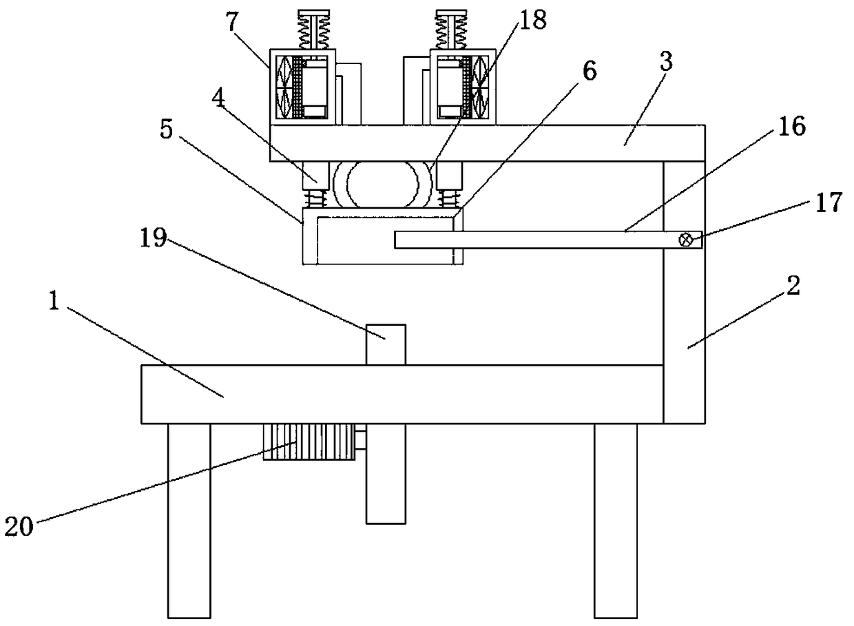
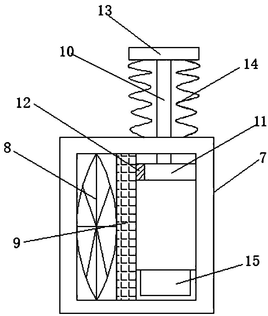
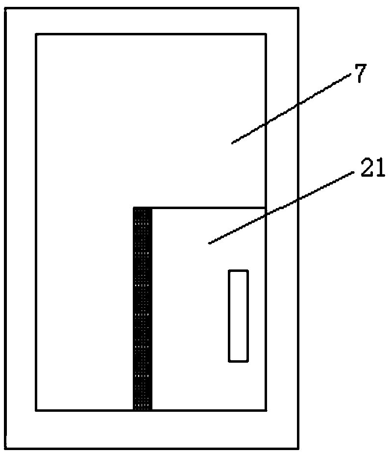
[0018] refer to Figure 1-3 , a dust removal device for plate cutting, comprising a cutting board 1, one end of the cutting board 1 is welded with a first supporting board 2, the top end of the first supporting board 2 is welded with a second supporting board 3 arranged horizontally, and the second supporting board 3 The bottom end of the telescopic rod 4 is connected with a symmetrically arranged telescopic rod 4, and the other end of the telescopic rod 4 is welded with a dust removal plate 5. The bottom end of the dust removal board 5 is provided with a groove 6, and a first Spring, the top of the second support plate 3 is welded with the processing b...
PUM
 Abstract
Description
Claims
Application Information