
Impurity removal device for plastic particles

A technology of plastic granules and feeding port, applied in the field of plastic granule impurity removal device, can solve the problems of difficulty in screening, damage to production equipment, high hardness and melting point of iron filings, and achieve the effect of increasing sliding distance and removing dust thoroughly.

Active Publication Date: 2018-12-18
怀宁县太阳家纺有限公司
View PDF5 Cites 2 Cited by
  • Summary
  • Abstract
  • Description
  • Claims
  • Application Information

AI Technical Summary

Problems solved by technology

[0002] Common plastic products are molded by melting plastic particles and then injecting them into molds. Plastic particles are in contact with various equipment during manufacturing, transportation and storage, and impurities must be avoided. Therefore, it is necessary to remove impurities from plastic particles. Commonly used screening However, common screening equipment can only screen out impurities such as dust, but cannot remove impurities such as iron filings, especially when the size of iron filings is close to plastic particles, it is more difficult to screen, and iron filings have higher hardness and melting point. High, melting plastic particles will cause damage to production equipment, so we propose a plastic particle removal device to solve the above problems

Method used


Image

  • Impurity removal device for plastic particles
  • Impurity removal device for plastic particles

Examples


Embodiment Construction

[0014] The following will clearly and completely describe the technical solutions in the embodiments of the present invention with reference to the accompanying drawings in the embodiments of the present invention. Obviously, the described embodiments are only some, not all, embodiments of the present invention. Based on the embodiments of the present invention, all other embodiments obtained by persons of ordinary skill in the art without making creative efforts belong to the protection scope of the present invention.

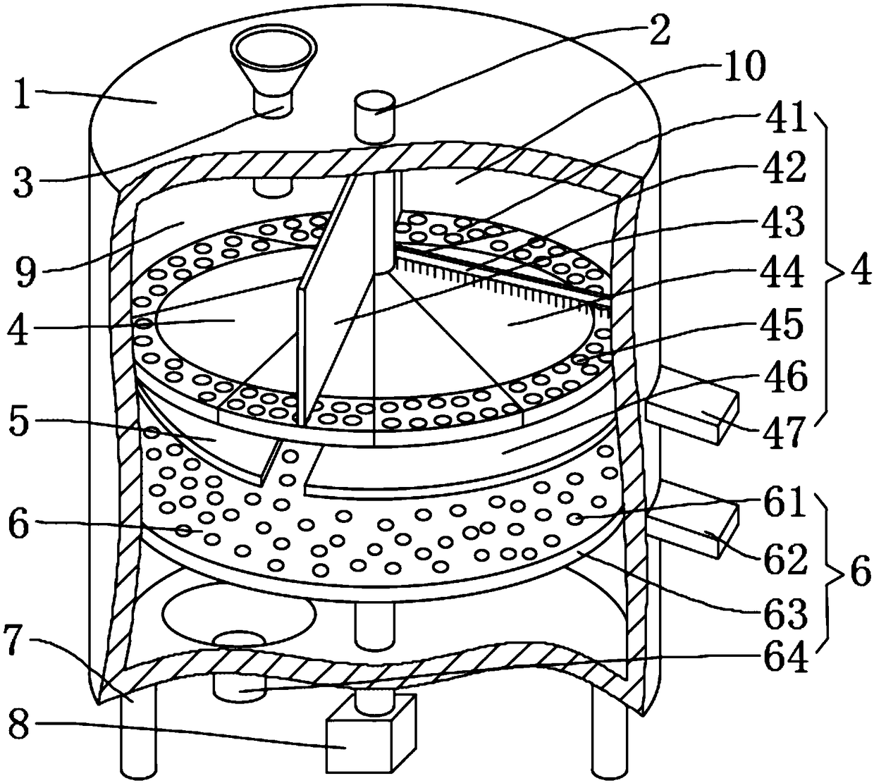
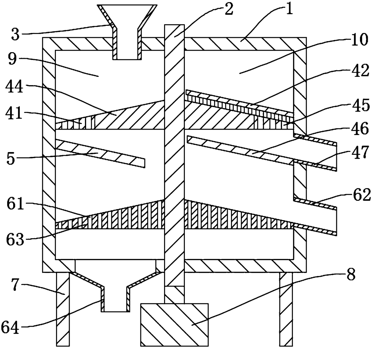
[0015] see Figure 1-2 , the present invention provides a technical solution: a plastic particle impurity removal device, comprising a housing 1, the top plate of the housing 1 is fixedly sleeved with the feed inlet 3, the housing 1 is fixedly installed with legs 7, the top plate and the bottom plate of the housing 1 Rotate and socket the vertical shaft 2 between them, the bottom end of the vertical shaft 2 is fixed to the rotating shaft with connection point ...


PUM


Abstract

The invention discloses an impurity removal device for plastic particles. The impurity removal device comprises a shell, a top plate of the shell is fixedly connected with a feeding inlet in a sleevedmode, and supporting legs are fixedly mounted at the shell part. A vertical shaft is rotationally connected between the top plate and a bottom plate of the shell in a sleeved mode, and the bottom endof the vertical shaft is fixedly connected with a rotary shaft of a motor. An iron removal device is arranged above an inner cavity of the shell, and a sliding plate is fixedly mounted on the position, below the iron removal device, on the inner wall of the shell. A dust removal device is fixedly connected to the position, below the sliding plate, on the vertical shaft in a sleeving mode. The plastic particles fall onto the iron removal device from the feeding inlet, and the iron removal device removes iron scrap, similar to the plastic particles in size, in the plastic particles; and the plastic particles fall onto the sliding plate and evenly fall onto the center of the dust removal device along the sliding plate, the plastic particles slide to the edges of the dust removal device fromthe center of the dust removal device, and thus the sliding distance of the plastic particles is increased, so that dust is removed sufficiently.

Description

technical field [0001] The invention relates to the technical field of plastic product equipment, in particular to a plastic particle impurity removal device. Background technique [0002] Common plastic products are molded by melting plastic particles and then injecting them into molds. Plastic particles are in contact with various equipment during manufacturing, transportation and storage, and impurities must be avoided. Therefore, it is necessary to remove impurities from plastic particles. Commonly used screening However, common screening equipment can only screen out impurities such as dust, but cannot remove impurities such as iron filings, especially when the size of iron filings is close to plastic particles, it is more difficult to screen, and iron filings have higher hardness and melting point. High, melting plastic particles will cause damage to the production equipment, so we propose a plastic particle removal device to solve the above problems. Contents of the...

Claims


Application Information

Patent Timeline
IPC IPC(8): B29B13/10
CPCB29B13/10
Inventor 郝结干
Owner 怀宁县太阳家纺有限公司
Learn More