A pushing type drainage trolley

A push-type, trolley technology, used in trolleys, motor vehicles, multi-axle trolleys, etc., can solve the problems of large volume and energy consumption of special cleaning equipment, inability to operate mechanical equipment quickly, and inability to meet the fast pace of cities, saving manpower and material resources. , The effect of removing impurities is good, and the effect of solving corners

Active Publication Date: 2018-12-18
NORTH CHINA UNIV OF WATER RESOURCES & ELECTRIC POWER
View PDF7 Cites 6 Cited by
  • Summary
  • Abstract
  • Description
  • Claims
  • Application Information

AI Technical Summary

Problems solved by technology

The unevenness of the road surface due to vehicle rolling or road quality is very easy to form small puddles of different sizes after the rain, causing inconvenience to citizens' travel, affecting the appearance of the city and requiring the sanitation company to organize a lot of manpower and material resources to clean up
According to statistics, since most sanitation companies lack equipment for clearing stagnant water and the special cleaning equipment consumes a lot of energy and is not easy to carry, so the current cleanup of low-lying areas and waterlogged roads mainly relies on a large amount of manpower to clean up, such Work efficiency is far from meeting the fast-paced needs of the city
Moreover, according to relevant statistics, the aging trend of sanitation workers in China is obvious and their education level is generally low. They cannot quickly operate modern mechanical equipment and heavy physical labor has a great impact on the health of workers.

Method used


Image

  • A pushing type drainage trolley
  • A pushing type drainage trolley
  • A pushing type drainage trolley

Examples


Embodiment Construction

[0024] The present invention will be described in detail below in conjunction with accompanying drawing and specific embodiment, and present embodiment is based on the premise of technical scheme of the present invention, has provided detailed implementation and specific operation process, but protection scope of the present invention is not limited to following implementation example.

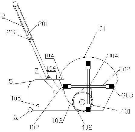
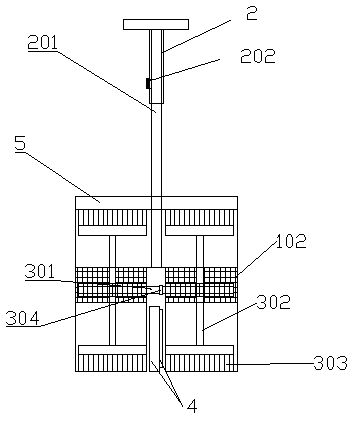
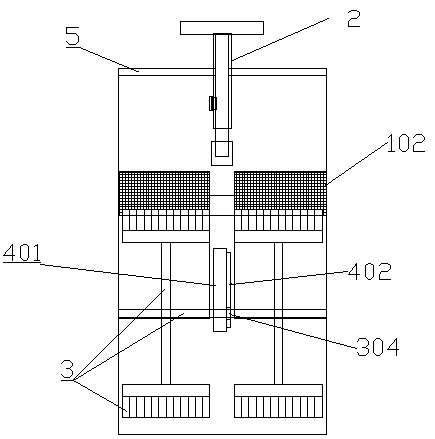
[0025] As shown in the figure, the present invention is a push type drainage trolley, comprising a push rod 2, a vehicle body 1, a drainage device 3 arranged inside the vehicle body 1, and a driving device 4 for driving the drainage trolley to run, the vehicle body 1, the push rod 2. The drainage device 3 and the driving device 4 can be made of stainless steel, which is strong and durable. The vehicle body 1 includes a shell 101, and the middle part of the shell 101 is provided with a filter socket 106 inclined along its width direction. A plurality of slots are set, the filter screen socket 1...


PUM

PropertyMeasurementUnit
radiusaaaaaaaaaa
widthaaaaaaaaaa
lengthaaaaaaaaaa

Abstract

The invention relates to a pushing type drainage trolley including a pushrod, a trolley Body, a draining device and a driving device, The trolley body comprises a housing, A filter socket is arrangedin the middle of the shell, A filter screen is inserted into the filter screen socket, A low end of that plug plate is provided with a baffle plate, the plug plate and the baffle plate divide the shell into a water storage chamber and a cleaning chamber, and the wat drainage device is arranged in the cleaning chamber through a filter net, the water drainage device comprises a rotating shaft, a brush rod and a brush head, a driving wheel is pierced in the center of the rotating shaft, a driving device is arranged below the driving wheel, a push rod is arranged above the water storage chamber, and a roller is arranged below the water storage chamber; The drainage trolley of the invention drives the brush rod and the brush head to rotate rapidly in the traveling process through the structureof the drainage device and the like, sweeps water into the water storage chamber with high efficiency, filters impurities through a filter screen, has good effect of removing impurities, can quickly clean the drainage, is convenient to use, and saves manpower and material resources.

Description

technical field [0001] The invention relates to the field of urban road cleaning, in particular to a push type drainage trolley. Background technique [0002] In recent years, with the rapid economic and social development, a large number of roads have been built in various cities, and the area of ​​urban hardened areas has increased significantly. However, the road infrastructure is relatively lagging behind, and the problem of drainage facilities is particularly prominent. Small puddles of different sizes are easily formed after rain due to vehicle rolling or road quality, causing inconvenience to citizens' travel, affecting the appearance of the city and requiring sanitation companies to organize a lot of manpower and material resources to clean them up. According to statistics, since most sanitation companies lack equipment for clearing stagnant water and the special cleaning equipment consumes a lot of energy and is not easy to carry, so the current cleanup of low-lyin...

Claims


Application Information

Patent Timeline
Patent Type & Authority Applications(China)
IPC IPC(8): B62B3/02B62B5/06E01H1/10B01D29/00
CPCB01D29/00B62B3/02B62B5/06E01H1/101
Inventor 王博焦延涛吴瀚仲深意颜廷松
Owner NORTH CHINA UNIV OF WATER RESOURCES & ELECTRIC POWER
Why Eureka
Try Eureka