
shuttle embroidery machine

An embroidery machine and shuttle technology, applied in the field of shuttle embroidery machines, can solve problems such as harmfulness and achieve the effect of low noise

Inactive Publication Date: 2021-07-16
LAESSER AG
View PDF6 Cites 0 Cited by
  • Summary
  • Abstract
  • Description
  • Claims
  • Application Information

AI Technical Summary

Problems solved by technology

Thus, the pushing movement prevented by these elastic elements and the wear of elements no longer needed here are transferred to wear on the shuttle path and to the linear guide elements arranged obliquely to the vertical with respect to the drive beam, as well as by the link The spring elastic elements on the shuttle embroidery machine cause inherently harmful vibrations

Method used


Image

  • shuttle embroidery machine
  • shuttle embroidery machine
  • shuttle embroidery machine

Examples


Embodiment Construction

[0073] The present invention will be described in detail below in conjunction with the accompanying drawings.

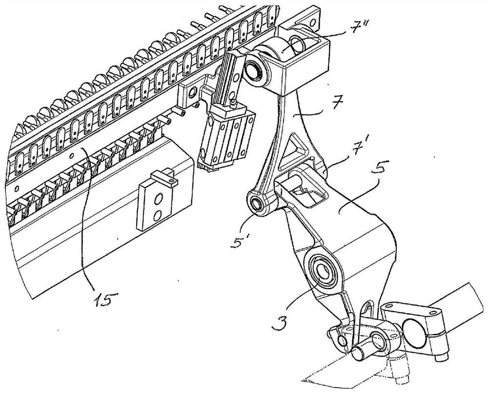
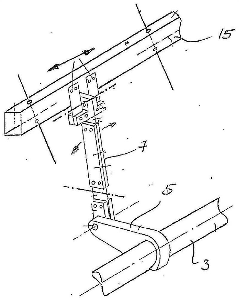
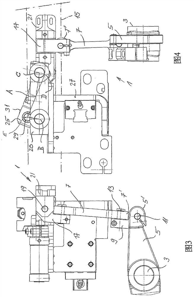
[0074] figure 1 The prior art shown is EP 1 595 990, in EP 1 595 990 Figure 4 Its components and working principles are described in detail in the relevant description of the . According to such an embodiment of the transmission device for the drive beam, the drive beam is supported on several guide rods in a displaceable manner on guides inclined to the vertical. The inclination angle relative to the vertical line is preferably 15°. The hoisting drive for driving the beam and having a crank linkage consisting of a crank and a connecting rod moves precisely vertically. In order to compensate for the lateral movement of the drive beam during its movement, a horizontal shaft is arranged on the drive beam, and the transmission rod / link is supported on the shaft in a manner that can move transversely to the transmission direction, so that the drive beam Lateral move...


PUM


Abstract

A shuttle embroidery machine, wherein a drive beam of the shuttle embroidery machine moves up and down on a movement path inclined to the vertical through a crank linkage (5, 7, 25, 31 and 33). The linear motion path is preferably achieved by a linkage that snaps onto the drive beam without the need for linear guide members.

Description

technical field [0001] The invention relates to a shuttle embroidery machine. Background technique [0002] Shuttle embroidery machines have been known for more than a century and work according to a two-thread system, ie one needle thread and one shuttle thread, wherein for each stitch the needle thread is wound by the shuttle thread. The front needle provided with the small hole conveys the needle thread through the sewing material to the back side of the sewing material, and the needle thread forms a loop during the withdrawal of the sewing needle. Subsequently, a shuttle containing the shuttle thread is passed through the loop. Shuttle embroidery machines include a large number of stitches arranged in a row and a corresponding number of needles and shuttles. There is a drive beam that moves the shuttle up and down in a slightly vertically inclined position. [0003] EP 1 595 990 discloses a shuttle embroidery machine with a drive beam vibrating due to a crank mechanis...

Claims


Application Information

Patent Timeline
Patent Type & Authority Patents(China)
IPC IPC(8): D05C11/18
CPCD05C11/18
Inventor 法兰兹·拉瑟汉诺·努斯堡摩
Owner LAESSER AG
Features
  • Generate Ideas
  • Intellectual Property
  • Life Sciences
  • Materials
  • Tech Scout
  • Unparalleled Data Quality
  • Higher Quality Content
  • 60% Fewer Hallucinations
Learn More