
Assembly type concrete frame filling wall structure system and construction method thereof

A concrete and infill wall technology, applied in the direction of walls, building components, building structures, etc., can solve the problems that the main frame of the infill wall cannot be deformed together, the interface is prone to slip damage, and the infill wall is damaged, etc., and achieves fast and convenient construction. Install in place, improve the effect of construction

Active Publication Date: 2018-12-18
HEBEI INSTITUTE OF ARCHITECTURE AND CIVIL ENGINEERING
View PDF7 Cites 9 Cited by
  • Summary
  • Abstract
  • Description
  • Claims
  • Application Information

AI Technical Summary

Problems solved by technology

[0006] The purpose of the present invention is to provide a prefabricated concrete frame filling wall structure system and its construction method to solve the problem that the filling wall acts directly on the main structure as a line load in the prior art, and the force is unreasonable; the filling wall adopts blocks, The interface between the block and the mortar is prone to slip damage; the infill wall and the main frame are connected by tie bars, the main frame of the infill wall cannot be deformed cooperatively, and the infill wall is seriously damaged.

Method used


Image

  • Assembly type concrete frame filling wall structure system and construction method thereof
  • Assembly type concrete frame filling wall structure system and construction method thereof
  • Assembly type concrete frame filling wall structure system and construction method thereof

Examples


Embodiment Construction

[0038] In order to make the technical means, innovative features, goals and effects achieved by the present invention easy to understand, the present invention will be further described below.

[0039] The examples described here are specific specific implementations of the present invention, and are used to illustrate the concept of the present invention. They are all explanatory and exemplary, and should not be construed as limiting the implementation of the present invention and the scope of the present invention. In addition to the embodiments described here, those skilled in the art can also adopt other obvious technical solutions based on the claims of the application and the contents disclosed in the description, and these technical solutions include adopting any obvious changes made to the embodiments described here. Replacement and modified technical solutions.

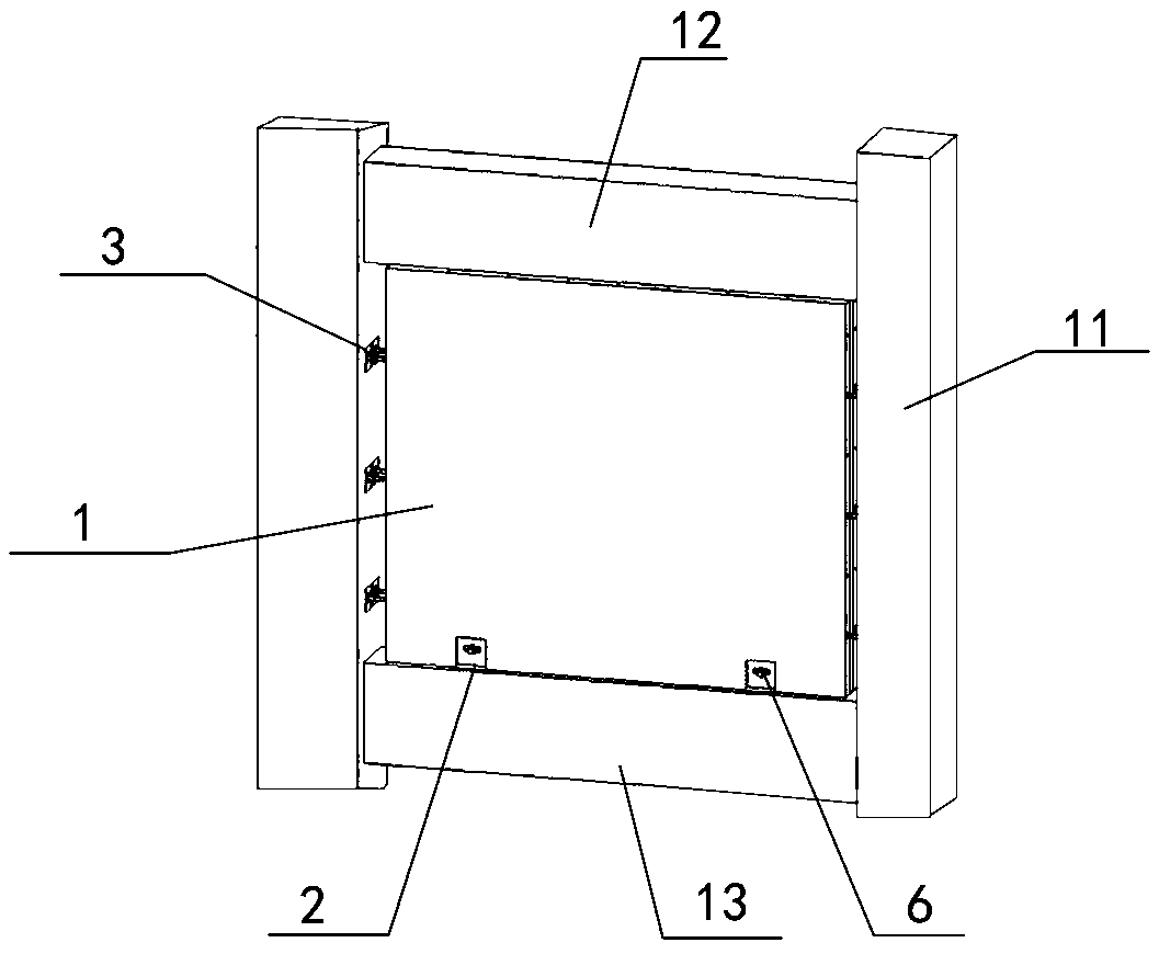
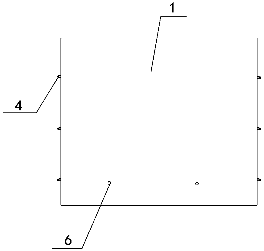
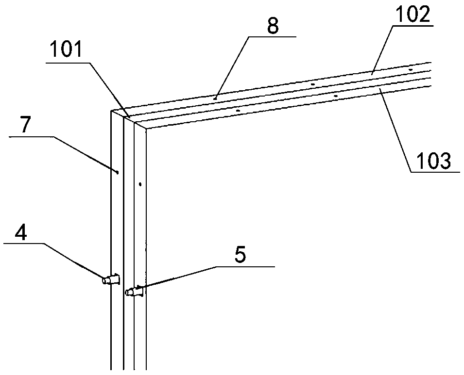
[0040] Such as Figure 1-7 It is a prefabricated concrete frame infill wall structure system, including a...


PUM


Abstract

The invention discloses an assembly type concrete frame filling wall structure system. The system comprises a concrete frame and a prefabricated filling wallboard, the concrete frame is rectangular and comprises frame columns, an upper frame beam and a lower frame beam, and angle steel connecting pieces are welded to the top of the lower frame beam; box connecting pieces are pre-buried at the inner sides of the frame columns at intervals, and the box connecting pieces comprise cuboid shells and connecting screw rods. The two ends of each main transverse construction steel bar in the prefabricated filling wallboard extend out of the two sides of the prefabricated filling wallboard, and the two ends of each main transverse construction steel bar are each connected with one end of a straightthreaded sleeve; the other end of each straight thread sleeve is connected with a connecting screw rod, and then the prefabricated filling wallboard is connected between the frame columns. Bolts are pre-buried at the bottom of the prefabricated filling wallboard, one end of each bolt penetrates through the corresponding angle steel connecting piece, and then the bottom of the prefabricated fillingwallboard is connected with the lower frame beam.

Description

technical field [0001] The invention relates to the field of construction engineering, in particular to a filling wall structure system and a construction method thereof. Background technique [0002] At present, the frame-fill wall structure system is a commonly used structural system. Due to the neglect of the fill wall in the design and construction process, the damage of the fill wall during the earthquake is very serious. [0003] From a design point of view, for the frame-filled wall structure system, the filled wall is usually directly acted on the main structure as a line load, without considering the influence of the filled wall on the main structure, which is inconsistent with the actual force of the structure, so the seismic damage of the filled wall is compared serious. [0004] From the perspective of construction, most of the current filling walls adopt masonry structure, using small concrete blocks or perforated bricks, etc. The construction process is cumber...

Claims


Application Information

Patent Timeline
Patent Type & Authority Applications(China)
IPC IPC(8): E04B2/64E04B1/98E04H9/02E04C2/288
CPCE04B2/562E04B2/64E04C2/2885E04H9/021
Inventor 麻建锁郭腾蔡焕琴陈硕齐梦程岚强亚林张敏马相楠祁尚文蔡妍
Owner HEBEI INSTITUTE OF ARCHITECTURE AND CIVIL ENGINEERING
Learn More