
Power battery top cover structure

A power battery, top cover technology, applied in the direction of battery cover/end cover, structural parts, battery pack components, etc., can solve the problems of cracking, disconnection, leakage of the joint surface, etc., and achieve the effect of avoiding cracking or even disconnection

Active Publication Date: 2020-07-24
CONTEMPORARY AMPEREX TECH CO
View PDF7 Cites 0 Cited by
  • Summary
  • Abstract
  • Description
  • Claims
  • Application Information

AI Technical Summary

Problems solved by technology

[0004] However, since the pole not only plays a conductive role in the top cover of the power battery, but is also used for fixing the first sealing member and the insulating member, it will be subjected to the extrusion stress of the first sealing member after assembly
These extrusion stresses will push the copper part and the aluminum part to the upper and lower sides of the top cover respectively. The above joint surface is cracked or even disconnected, thus causing liquid leakage, which is more likely to occur when the diameter of the pole is small

Method used


Image

  • Power battery top cover structure
  • Power battery top cover structure
  • Power battery top cover structure

Examples


Embodiment Construction

[0068] The present application will be described in further detail below through specific embodiments and in conjunction with the accompanying drawings. The "front", "rear", "left", "right", "upper" and "lower" mentioned in the text are all referred to the power battery top cover structure in the attached drawings.

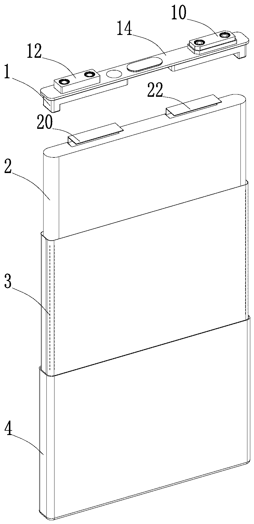
[0069] Such as figure 1As shown, the embodiment of the present application provides a power battery, including a power battery top cover structure 1 , a bare cell 2 , an insulating layer 3 of the bare cell, and a case 4 . The bare cell 2 includes a positive electrode sheet, a negative electrode sheet, and a separator between the positive electrode sheet and the negative electrode sheet. The bare cell 2 is wrapped with the insulating layer 3 of the bare cell and put into the casing 4, and then covered with the top cover structure of the power battery. 1 and filled with electrolyte to form a complete power battery.

[0070] Such as figure 2 As shown, the power b...


PUM


Abstract

The present application relates to the field of energy storage devices, and in particular to a power battery top cover structure, including a first electrode assembly, a second electrode assembly, and a top cover sheet. The first electrode assembly includes a first pole, a first sealing member, and a first electrode assembly. The connecting block, the first pole includes an upper section and a lower section, the material of the upper section and the first connecting block has a first base metal, the material of the lower section has a second base metal, the upper section has a step portion, the lower section is connected to the bottom surface of the upper section, and the top cover sheet It has a first pole hole, the upper section passes through the first pole hole, the stepped part and the lower section are located under the top cover sheet, the first sealing member includes a homogeneous sealing part and a lateral extension part, and the cylindrical sealing part is sleeved on the upper section, The lateral extension part is located between the lower surface of the top cover sheet and the stepped part, the top of the upper section is connected with the first connection block, and the second electrode assembly is attached to the top cover sheet. The power battery top cover structure provided by the embodiment of the present application can effectively prevent the joint surface of the upper section and the lower section from cracking or even breaking.

Description

technical field [0001] The present application relates to the field of energy storage devices, in particular to a power battery top cover structure. Background technique [0002] In the non-aqueous electrolyte secondary battery, aluminum or an aluminum alloy that is insoluble in the non-aqueous electrolyte at the positive electrode potential is suitably used as a constituent material of the positive electrode pole. Copper, which is not alloyed with the negative electrode active material, is often used as a constituent material of the negative electrode pole. [0003] When the power battery is grouped, the busbar needs to be welded to the connection block of the positive electrode or the connection block of the negative electrode. Since the busbar is mostly made of a single material (such as aluminum or copper), the melting point of aluminum is lower than that of copper and the specific heat capacity is higher. , it is impossible to easily weld the copper and aluminum materi...

Claims


Application Information

Patent Timeline
Patent Type & Authority Patents(China)
IPC IPC(8): H01M2/04H01M50/147H01M50/176H01M50/184H01M50/188H01M50/55H01M50/553H01M50/562H01M50/566H01M50/567
CPCH01M50/147H01M50/553H01M50/55H01M50/176H01M50/567H01M50/184H01M50/566H01M50/188H01M50/562H01M10/05Y02E60/10
Inventor 邢承友李全坤王鹏郭志君
Owner CONTEMPORARY AMPEREX TECH CO
Learn More