Filter with automatic dredging function

A filter, automatic technology, applied in the direction of fixed filter element filter, filter separation, machine/engine, etc., can solve the problem that the filter is lifted to the liquid level for cleaning, separated from the filter screen and returned to the liquid storage tank, and the pump cannot suck. problems such as the upper medium, to achieve the effect of good economy, low price and simple structure

Pending Publication Date: 2018-12-18
辽宁格瑞特泵业有限公司
View PDF0 Cites 1 Cited by
  • Summary
  • Abstract
  • Description
  • Claims
  • Application Information

AI Technical Summary

Problems solved by technology

[0002] The wastewater generated in the production process of the petroleum and petrochemical industry is often mixed with a large amount of impurities. These impurities have complex components, even including bottles, rags, etc. These impurities will be adsorbed on the outside of the filter screen of the inlet pipe and block the holes on the filter screen, causing the pump to fail to absorb the medium. , the filter needs to be cleaned frequently
Small particles of impurities such as sand and gravel can enter the filter screen with the suction medium and be discharged together with the waste water, while larger impurities such as bottles and rags cannot enter the filter screen and are discharged to the outlet pipeline together with the suction medium. When the pump is stopped, there will be no suction at the inlet of the inlet pipe, and large pieces of impurities will break away from the filter and return to the liquid storage tank. When the cleaned filter is put into the tank again for pumping water, it will be absorbed by the suction of the pump inlet to the filter again, causing Secondary clogging, and impurities in the pool accumulate more and more over time
Moreover, some tanks have special structures, and the pipelines are bent and non-straight in many places. The filter installed at the inlet of the pump suction pipeline cannot be lifted up to the liquid level for cleaning. It is an urgent problem to clean the filter directly below the surface and remove the large impurities accumulated in the tank with the liquid surface.

Method used


Image

  • Filter with automatic dredging function
  • Filter with automatic dredging function
  • Filter with automatic dredging function

Examples


Embodiment 1

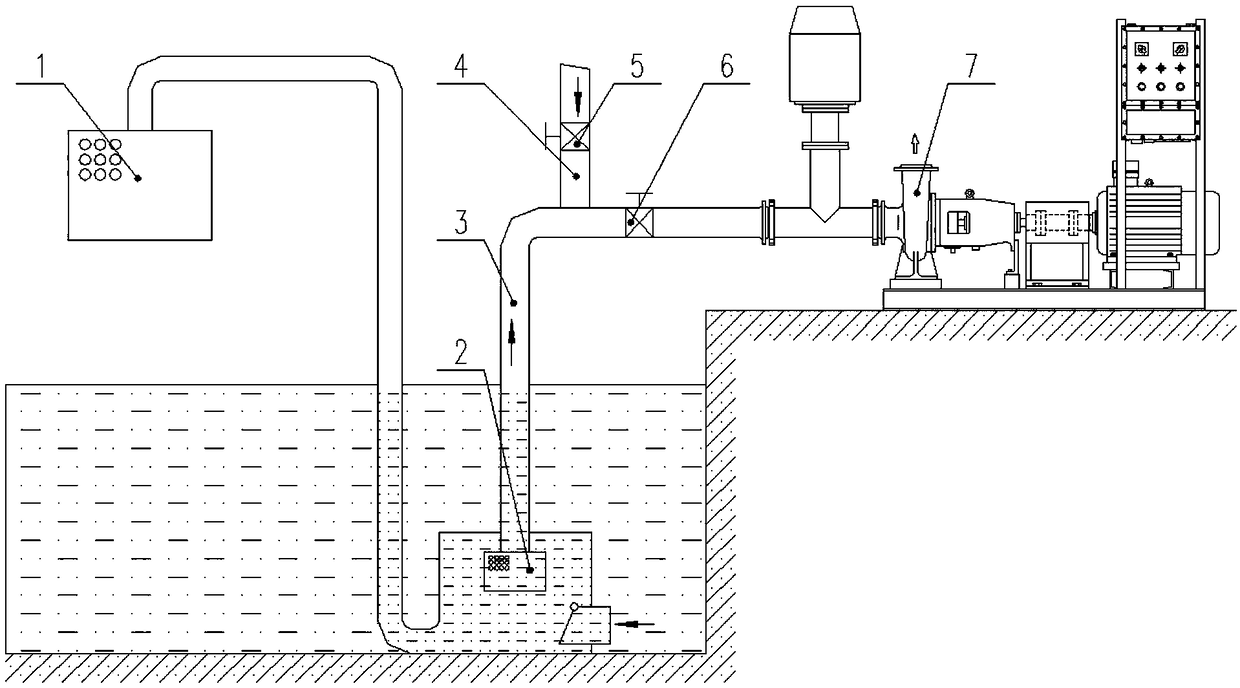
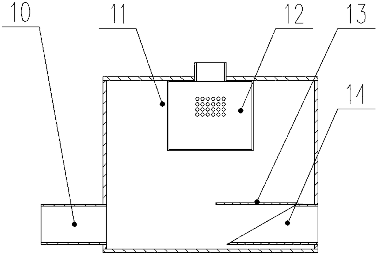
[0029] Such as figure 1 and figure 2 As shown, an automatic dredging filter 2, the automatic dredging filter 2 includes an impurity collection box 11, the impurity collection box 11 is provided with a suction line filter 12, a one-way valve 13 and a liquid inlet pipe 14, and the suction line filters The net 12 is connected to the inlet of the suction pipeline 3, and is used to intercept impurities to prevent them from entering the suction pipeline 3. The liquid inlet pipe 14 is connected to the tank, and is used to introduce the medium and impurities in the tank into the impurity collection box 11, and the one-way valve 13 is set The mouth of the liquid inlet pipe 14 is used to prevent the impurities entering the impurity collection box 11 from returning to the tank. , the slag discharge pipe 10 is connected with the filtrate net 1, the filtrate net 1 is provided with holes for discharging the medium, the automatic dredging filter 2 is installed under the liquid surface, and...

Embodiment 2

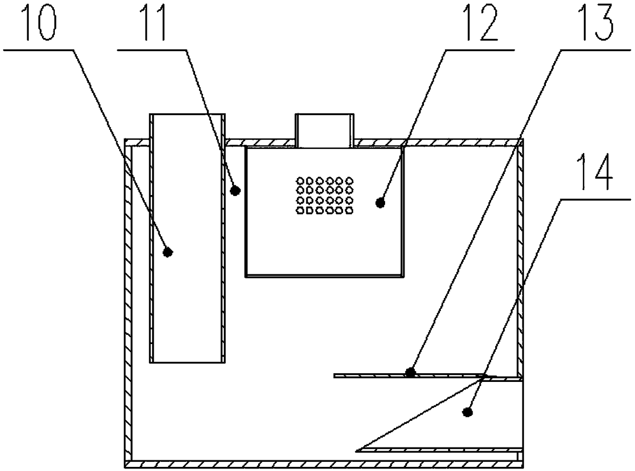
[0034] Such as image 3 As shown, an automatic dredging filter 2, the automatic dredging filter 2 includes an impurity collection box 11, the impurity collection box 11 is provided with a suction line filter 12, a one-way valve 13 and a liquid inlet pipe 14, and the suction line filters The net 12 is connected to the inlet of the suction pipeline 3, and is used to intercept impurities to prevent them from entering the suction pipeline 3. The liquid inlet pipe 14 is connected to the tank, and is used to introduce the medium and impurities in the tank into the impurity collection box 11, and the one-way valve 13 is set The mouth of the liquid inlet pipe 14 is used to prevent the impurities entering the impurity collection box 11 from returning to the tank. , The slag discharge pipe 10 is connected to the filtrate net 1, and the filtrate net 1 is provided with holes for discharging the medium. The automatic dredging filter 2 is installed under the liquid surface, the slag discha...

Embodiment 3

[0037] Such as Figure 4 and Figure 5 As shown, an automatic dredging filter 2, the automatic dredging filter 2 includes an impurity collection box 11, the impurity collection box 11 is provided with a suction line filter 12, a one-way valve 13 and a liquid inlet pipe 14, and the suction line filters The net 12 is connected to the inlet of the suction pipeline 3, and is used to intercept impurities to prevent them from entering the suction pipeline 3. The liquid inlet pipe 14 is connected to the tank, and is used to introduce the medium and impurities in the tank into the impurity collection box 11, and the one-way valve 13 is set The mouth of the liquid inlet pipe 14 is used to prevent the impurities entering the impurity collection box 11 from returning to the tank. , the slag discharge pipe 10 is connected with the filtrate net 1, the filtrate net 1 is provided with holes for discharging the medium, the automatic dredging filter 2 is installed on the ground, the slag disc...


PUM


Abstract

The invention provides a filter with an automatic dredging function, and belongs to the technical field of separation devices. The filter with the automatic dredging function is mounted at an inlet ofa suction pipeline and comprises an impurity collection box. A suction pipeline filter screen, a one-way valve and a liquid inlet pipe are arranged in the impurity collection box. The suction pipeline filter screen is connected with the inlet of the suction pipeline and is used for intercepting impurities so as to prevent the impurities from entering the suction pipeline. An air inlet pipeline isarranged on the suction pipeline and is used for inflating the filter with the automatic dredging function. The liquid inlet pipe communicates with a pool tank and is used for guiding media and impurities in the pool tank into the impurity collection box. The one-way valve is arranged at an opening of the liquid inlet pipe. The impurity collection box is provided with a slag discharging pipe. Thefilter with the automatic dredging function is simple in structure, easy to operate and capable of automatically removing impurities blocking meshes of the suction pipeline filter screen and intercepting and regularly discharging big impurities, which cannot be directly discharged from a pump outlet, in the pool tank and has economical performance and a good using effect.

Description

technical field [0001] The invention relates to the technical field of separation devices, in particular to an automatic desilting filter. Background technique [0002] The wastewater generated in the production process of the petroleum and petrochemical industry is often mixed with a large amount of impurities. These impurities have complex components, even including bottles, rags, etc. These impurities will be adsorbed on the outside of the filter screen of the inlet pipe and block the holes on the filter screen, causing the pump to fail to absorb the medium. , the filter needs to be cleaned frequently. Small particles of impurities such as sand and gravel can enter the filter screen with the suction medium and be discharged together with the waste water, while larger impurities such as bottles and rags cannot enter the filter screen and are discharged to the outlet pipeline together with the suction medium. When the pump is stopped, there will be no suction at the inlet ...

Claims


Application Information

Patent Timeline
Patent Type & Authority Applications(China)
IPC IPC(8): F04B53/20B01D35/02B01D35/16B01D29/33B01D29/92B01D29/66B01D29/50
CPCF04B53/20B01D29/33B01D29/50B01D29/66B01D29/92B01D35/02B01D35/16
Inventor 苏循德崔正军
Owner 辽宁格瑞特泵业有限公司
Why Eureka
Try Eureka