Thrust cylindrical roller spherical bearing for differential mechanism assembly and machining method of thrust cylindrical roller spherical bearing

A technology of cylindrical roller and spherical bearings, applied in the direction of bearing elements, shafts and bearings, mechanical equipment, etc., can solve the problems of gasket and shell wear, aggravate the wear of the gasket and shell, and the shell and gasket , to achieve the effect of eliminating friction and wear, improving service life and reducing friction and wear

Pending Publication Date: 2018-12-18
洛阳华冠齿轮股份有限公司
View PDF9 Cites 2 Cited by
  • Summary
  • Abstract
  • Description
  • Claims
  • Application Information

AI Technical Summary

Problems solved by technology

[0003] When the differential assembly is in working condition, whether the car is going straight or turning, the two side gears in the differential are always rotating, and the spacer between the side gear gasket and the housing and the side gear is always It will be in relative rotation from time to time. At this time, there will be friction between the gasket and the housing, the gasket and the side gear, and over time, it will cause wear on the gasket and the housing; when the car turns, the differential speed In addition to revolution, the planetary gear in the gear will also produce self-rotation. At this time, the planetary gear gasket will also be worn due to sliding friction; Under the situation, the instantaneous axial force increases geometrically, and when the gear rotates, the friction force increases sharply, the shell and the gasket wear more seriously, and sometimes there will be burning and bonding between the gasket and the gear joint surface. The continuous relative rotation between the gasket and the shell will intensify the wear between the gasket and the shell

Method used


Image

  • Thrust cylindrical roller spherical bearing for differential mechanism assembly and machining method of thrust cylindrical roller spherical bearing
  • Thrust cylindrical roller spherical bearing for differential mechanism assembly and machining method of thrust cylindrical roller spherical bearing
  • Thrust cylindrical roller spherical bearing for differential mechanism assembly and machining method of thrust cylindrical roller spherical bearing

Examples


Embodiment Construction

[0026] The technical solutions in the embodiments of the present invention will be clearly and completely described below in conjunction with the accompanying drawings in the embodiments of the present invention. Obviously, the described embodiments are only a part of the embodiments of the present invention, rather than all the embodiments. Based on the embodiments of the present invention, all other embodiments obtained by those of ordinary skill in the art without creative work shall fall within the protection scope of the present invention.

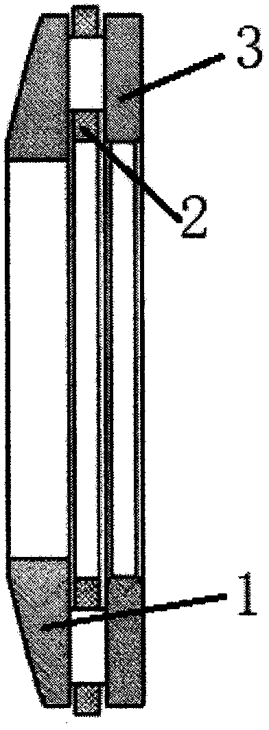
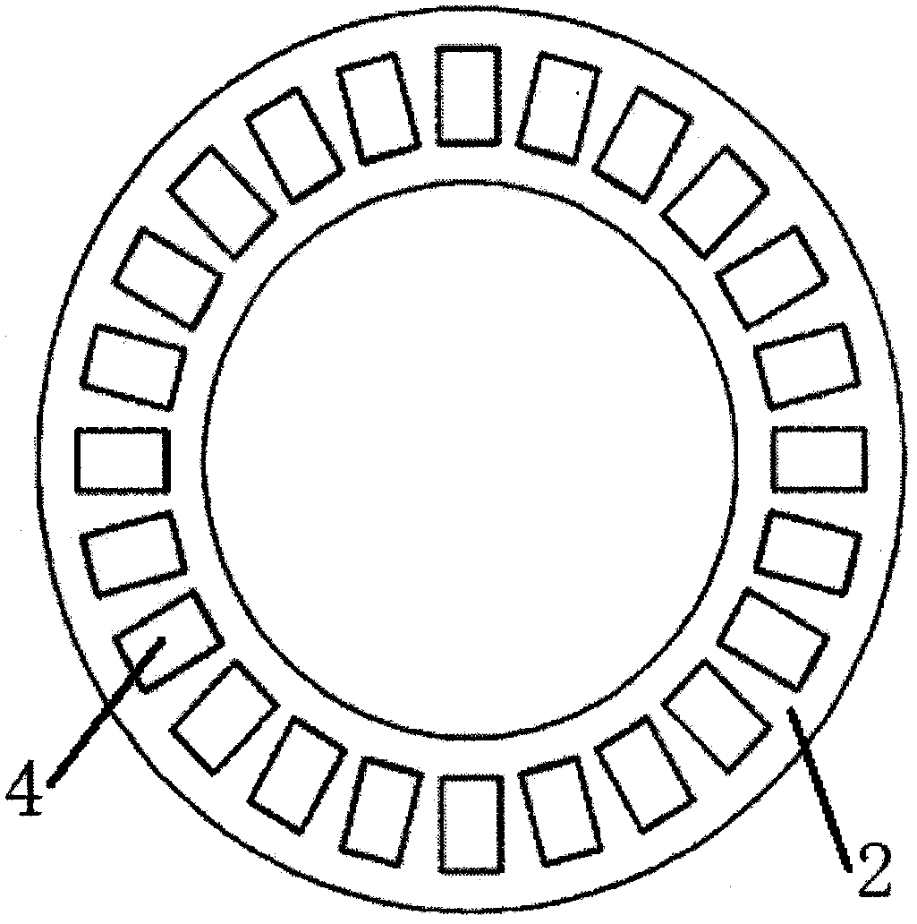
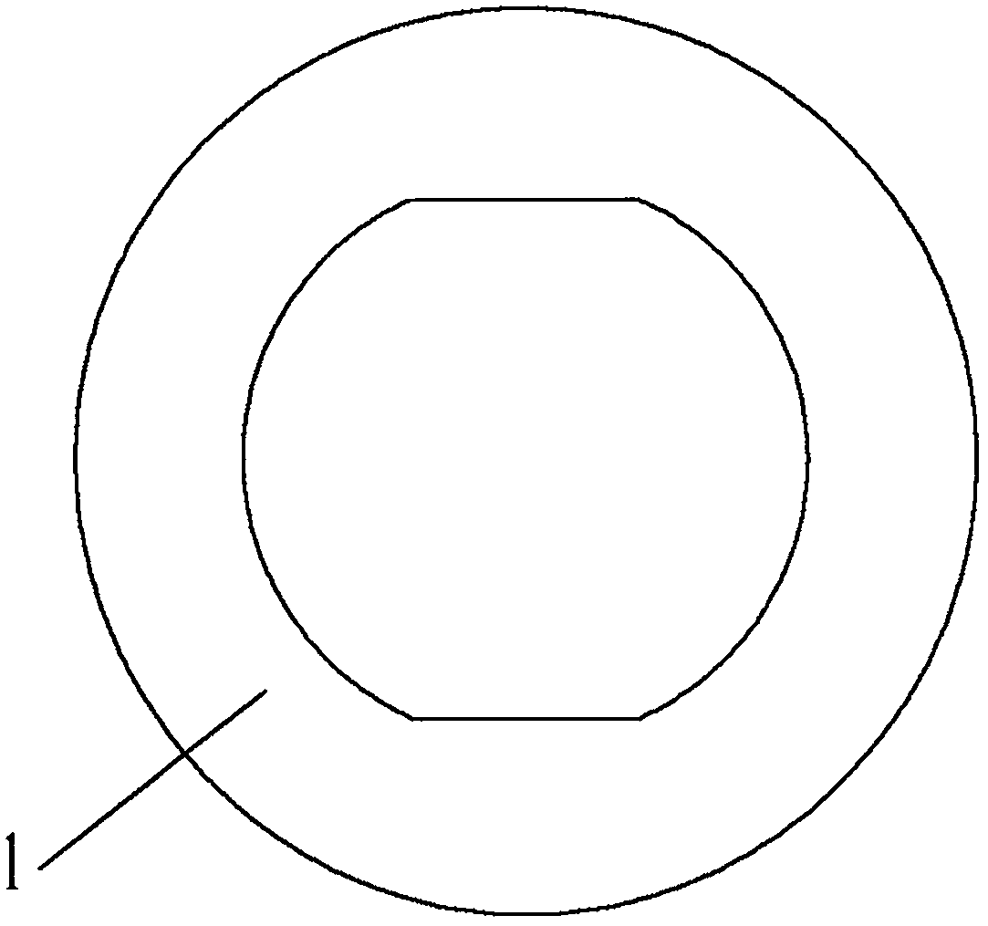
[0027] Reference Figure 1-3 , A thrust cylindrical roller spherical bearing for differential assembly, including seat ring 3, the seat ring is an annular thin gasket and the inner diameter and outer diameter of the seat ring 3 are two concentric circles, the outer diameter and the planetary gear The concave stop is matched. One side of the seat ring 3 is connected with a cage 2. The inner diameter of the cage 2 is the same as that of th...


PUM

PropertyMeasurementUnit
hardnessaaaaaaaaaa
hardnessaaaaaaaaaa

Abstract

The invention discloses a thrust cylindrical roller spherical bearing for a differential mechanism assembly and a machining method of the thrust cylindrical roller spherical bearing. The thrust cylindrical roller spherical bearing comprises a seat ring. The inner diameter and the outer diameter of the seat ring are two concentric circles, and the outer diameter is matched with a concave spigot ofa planetary gear. One side of the seat ring is connected with a holder. The inner diameter of the holder is the same as that of the seat ring. The inner diameter of the seat ring and the inner diameter of the holder are in small clearance fit with a cross shaft. One side of the holder is connected with a shaft ring. The shaft ring is of a structure with one end being a plane, the other end being aconvex spherical surface, an inner hole being in a non-continuous round shape and the thickness being a non-constant value. After the thrust cylindrical roller spherical bearing replaces an originalspherical surface gasket, inherent sliding friction between two parts with relative rotation or rotating tendency between original contact faces in the differential mechanism assembly is changed intorolling friction between the shaft ring, the seat ring and a roller of the bearing, and friction wear is reduced.

Description

Technical field [0001] The invention relates to the technical field of bearing manufacturing of a differential assembly, in particular to a thrust cylindrical roller spherical bearing for a differential assembly and a processing method thereof. Background technique [0002] Ordinary differentials are generally composed of two or four planetary gears, planetary gear carriers (integral differential housing and a word shaft or left and right differential housings and cross shafts), two half shaft gears and spherical gaskets , Half-shaft flat gasket and other parts. The power of the engine enters the differential through the transmission shaft and directly drives the planetary gear carrier. The planetary gear drives the half shaft gears that mesh with it. The two half shaft gears drive the matching left and right half shafts. Drive the left and right wheels respectively. The design requirements of the differential should meet: (left half shaft speed) + (right half shaft speed) = 2 ...

Claims


Application Information

Patent Timeline
Patent Type & Authority Applications(China)
IPC IPC(8): F16C33/58F16C33/46B23P15/00
CPCF16C33/46F16C33/58B23P15/003
Inventor 孟江涛杜煦民梅利红孟怡辰
Owner 洛阳华冠齿轮股份有限公司
Why Eureka
Try Eureka