An electric control brake device

A brake device and electrical control technology, which is applied in the direction of brake actuators, gear transmission mechanisms, mechanical equipment, etc., can solve the problems of excessive wear of friction linings, slow brake response speed, and increased cost of use of brake devices. , to achieve the effect of prolonging service life, increasing sensitivity and simple structure

Inactive Publication Date: 2019-12-06
CHANGSHA UNIVERSITY
View PDF8 Cites 0 Cited by
  • Summary
  • Abstract
  • Description
  • Claims
  • Application Information

AI Technical Summary

Problems solved by technology

[0002] The braking device (braking equipment) is the general term for all the braking and deceleration systems installed in the car. Its function is to slow down or stop the moving car, or keep the stopped car still. The structure and performance of the device are directly related to the safety of the vehicle and personnel, so it is considered as an important safety part of the car and is widely valued; however, the existing brake devices are generally mechanical hydraulic brakes, and the brake response speed is slow, and It is necessary to continuously step on the brake plate to keep the brake device in the braking state. The user cannot free his feet and restricts the user's activities. The two-petal brake shoe is used. Since the rotation angle of the brake shoe cannot be controlled, the outer side of the friction lining The inner side of the brake drum cannot be fully fitted, causing the friction lining to wear too quickly, and new friction linings need to be replaced frequently, which not only affects the use of the brake device, but also increases the use cost of the brake device, which cannot meet the actual needs. So we need to invent an electrically controlled braking device

Method used


Image

  • An electric control brake device
  • An electric control brake device
  • An electric control brake device

Examples


Embodiment Construction

[0014] In order to make the purpose, technical solutions and advantages of the embodiments of the present invention clearer, the technical solutions in the embodiments of the present invention will be clearly and completely described below in conjunction with the drawings in the embodiments of the present invention. Obviously, the described embodiments It is a part of embodiments of the present invention, but not all embodiments. Based on the embodiments of the present invention, all other embodiments obtained by persons of ordinary skill in the art without creative efforts fall within the protection scope of the present invention.

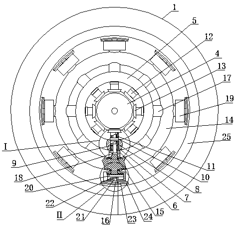
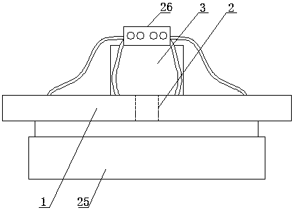
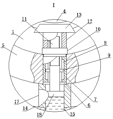
[0015]An electrically controlled braking device, as shown in the figure, includes a fixed plate 1, a first through hole 2 is opened in the middle of the front side of the fixed plate 1, and the rotating shaft of the motor 3 is installed in the first through hole 2, and the front of the motor 3 The side is fixedly connected with the rear side of th...


PUM


Abstract

The invention relates to an electrically-controlled braking device which comprises a fixed plate. A first through hole is formed in the middle of the front side of the fixed plate, and a rotating shaft of a motor is arranged in the first through hole through a bearing. The front side of the motor is fixedly connected with the rear side of the fixed plate, and a first bevel gear is fixedly arrangedat the front end of the rotating shaft of the motor. The front side of the fixed plate is fixedly connected with the rear side of a horizontal pipe, and the horizontal pipe is collinear with the center line of the first bevel gear. A plurality of second through holes are uniformly formed in the periphery of the horizontal pipe, and first stand pipes are fixedly arranged in the second through holes correspondingly. Bar-type sliding grooves being axially symmetric are correspondingly formed in the inner walls of the first stand pipes, and sliding blocks are movably arranged in the bar-type sliding grooves correspondingly and can slide correspondingly along the corresponding bar-type sliding groove. The electrically-controlled braking device is simple in structure and adopts electro-hydraulic braking, thereby retaining the stability of hydraulic braking, and also adding the sensitivity of electrical braking.

Description

technical field [0001] The invention belongs to the field of braking devices, in particular to an electrically controlled braking device. Background technique [0002] The braking device (braking equipment) is the general term for all the braking and deceleration systems installed in the car. Its function is to slow down or stop the moving car, or keep the stopped car still. The structure and performance of the device are directly related to the safety of the vehicle and personnel, so it is considered as an important safety part of the car and is generally valued; It is necessary to continuously step on the brake plate to keep the brake device in the braking state. The user cannot free his feet and restricts the user's activities. The two-petal brake shoe is used. Since the rotation angle of the brake shoe cannot be controlled, the outer side of the friction lining The inner side of the brake drum cannot be fully fitted, causing the friction lining to wear out too quickly, ...

Claims


Application Information

Patent Timeline
Patent Type & Authority Patents(China)
IPC IPC(8): F16D65/14F16D121/24F16D121/04F16D121/14F16D123/00
CPCF16D65/14F16D2121/04F16D2121/14F16D2121/24F16D2123/00
Inventor 冯婉张文娟张志刚
Owner CHANGSHA UNIVERSITY
Why Eureka
Try Eureka