Pneumatic element shock absorption device

A shock absorber and pneumatic component technology, which is applied in the direction of shock absorber, spring/shock absorber, shock absorber, etc., can solve the problems of reduced processing efficiency, economic loss, large impact force, etc., to improve processing efficiency, Effect of reducing economic loss and prolonging service life

Inactive Publication Date: 2018-12-18
ANHUI MUFAN ELECTRONICS TECH CO LTD
View PDF0 Cites 7 Cited by
  • Summary
  • Abstract
  • Description
  • Claims
  • Application Information

AI Technical Summary

Problems solved by technology

[0002] Pneumatic components are components that do work through the force generated by the pressure or expansion of gas, that is, the components that convert the elastic energy of compressed air into kinetic energy, such as cylinders, air motors and steam engines, etc. Pneumatic components are a form of power transmission, also known as The energy replacement device uses gas pressure to transfer energy. With the continuous development of the mechanical processing industry, the use of cylinders is becoming more and more frequent. When large parts are often processed, due to the large volume and heavy weight of the workpiece, the There will be a large impact force when rebounding. The ordinary cylinder does not have a limit buffer structure and a shock absorption structure, which is easy to cause damage to the cylinder, which reduces the processing efficiency and brings economic losses.

Method used


Image

  • Pneumatic element shock absorption device
  • Pneumatic element shock absorption device

Examples


Embodiment Construction

[0018] The following will clearly and completely describe the technical solutions in the embodiments of the present invention with reference to the accompanying drawings in the embodiments of the present invention. Obviously, the described embodiments are only some, not all, embodiments of the present invention. All other embodiments obtained by persons of ordinary skill in the art based on the embodiments of the present invention belong to the protection scope of the present invention.

[0019] According to an embodiment of the present invention, a shock absorbing device for a pneumatic element is provided.

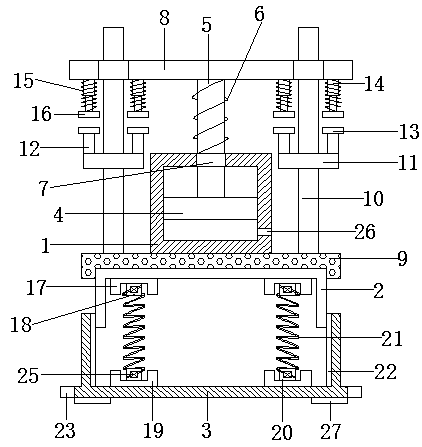
[0020] Such as Figure 1-2 As shown, a pneumatic element damping device according to an embodiment of the present invention includes a cylinder 1, an upper housing 2 and a lower housing 3, the inside of the cylinder 1 is provided with a piston 4, and the bottom of the piston 4 is provided with A piston rod 5, and the piston rod 5 extends to the top outside of the cylind...


PUM


Abstract

The invention discloses a pneumatic element shock absorption device comprising a cylinder, an upper shell and a lower shell. A piston is arranged in the cylinder. A piston rod is arranged at the bottom of the piston and extends to the top end of the outer side of the cylinder. A first spring is arranged on the portion, extending to the outer side of the cylinder, of the piston rod in a sleeving manner. A piston ring is installed at the connection position of the piston rod and the cylinder. A top plate is arranged on the top of the piston rod. An elastic plate is arranged at the bottom of thecylinder and is located on the top of the upper shell. Guide rails are arranged on the two lateral sides of the bottom of the elastic plate correspondingly. The guide rails extend upwards and penetrate the top. Annular limiting blocks are arranged on the middle portions of the guide rails correspondingly. The guide rails penetrate the annular limiting blocks. Supporting rods are perpendicularly arranged on the two lateral sides of each annular limiting block correspondingly. Installation blocks are arranged at the bottom ends of the two lateral sides of the lower shell correspondingly. An installation hole is formed in each installation block.

Description

technical field [0001] The invention relates to the field of pneumatic component protection devices, in particular to a pneumatic component shock absorber. Background technique [0002] Pneumatic components are components that do work through the force generated by the pressure or expansion of gas, that is, the components that convert the elastic energy of compressed air into kinetic energy, such as cylinders, air motors and steam engines, etc. Pneumatic components are a form of power transmission, also known as The energy replacement device uses gas pressure to transfer energy. With the continuous development of the mechanical processing industry, the use of cylinders is becoming more and more frequent. When large parts are often processed, due to the large volume and heavy weight of the workpiece, the When rebounding, a large impact force will be generated. The ordinary cylinder does not have a limit buffer structure and a shock absorption structure, which is easy to cau...

Claims


Application Information

Patent Timeline
Patent Type & Authority Applications(China)
IPC IPC(8): F16F13/00
CPCF16F13/007F16F2230/0023
Inventor 储孝伦薛绘晴
Owner ANHUI MUFAN ELECTRONICS TECH CO LTD
Why Eureka
Try Eureka