
Valve body capable of discharging small particles and liquid outlet device provided with valve body

A small particle, valve body technology, applied in the direction of valve device, valve operation/release device, valve details, etc., can solve the problems of small valve hole, valve hole blockage, increased workload, etc.

Inactive Publication Date: 2018-12-18
白斌将
View PDF6 Cites 0 Cited by
  • Summary
  • Abstract
  • Description
  • Claims
  • Application Information

AI Technical Summary

Problems solved by technology

[0002] Existing coffee machines, soybean milk machines, fruit juice machines, beverage machines, washing machines, dishwashers, tea set washing machines, etc. produce liquids with small powders, small particles, thick, residues, etc.; however, the existing solenoid valves The valve hole of the solenoid valve is relatively small. When the liquid with particles is discharged, the valve hole will be blocked. Usually, a filter structure is installed at the third port of the solenoid valve to block the particles outside the filter structure, which is convenient for the solenoid valve to drain, and the particles are blocked. When it is blocked at the filter structure, the user needs to clean up these particles, and the workload increases

Method used


Image

  • Valve body capable of discharging small particles and liquid outlet device provided with valve body
  • Valve body capable of discharging small particles and liquid outlet device provided with valve body
  • Valve body capable of discharging small particles and liquid outlet device provided with valve body

Examples


Embodiment Construction

[0036] In order to further explain the technical solution of the present invention, the present invention will be described in detail below through specific examples.

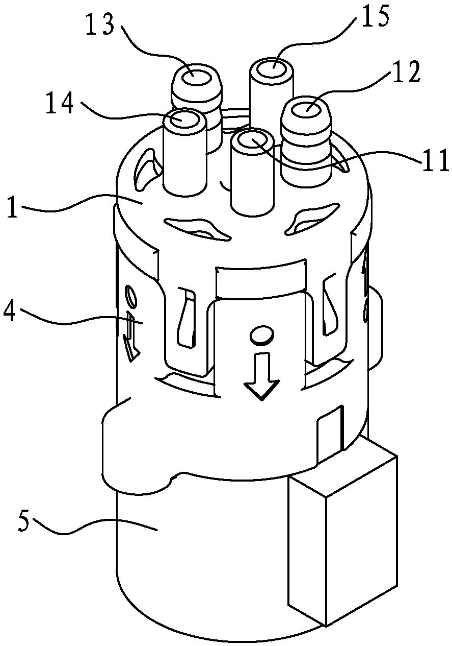
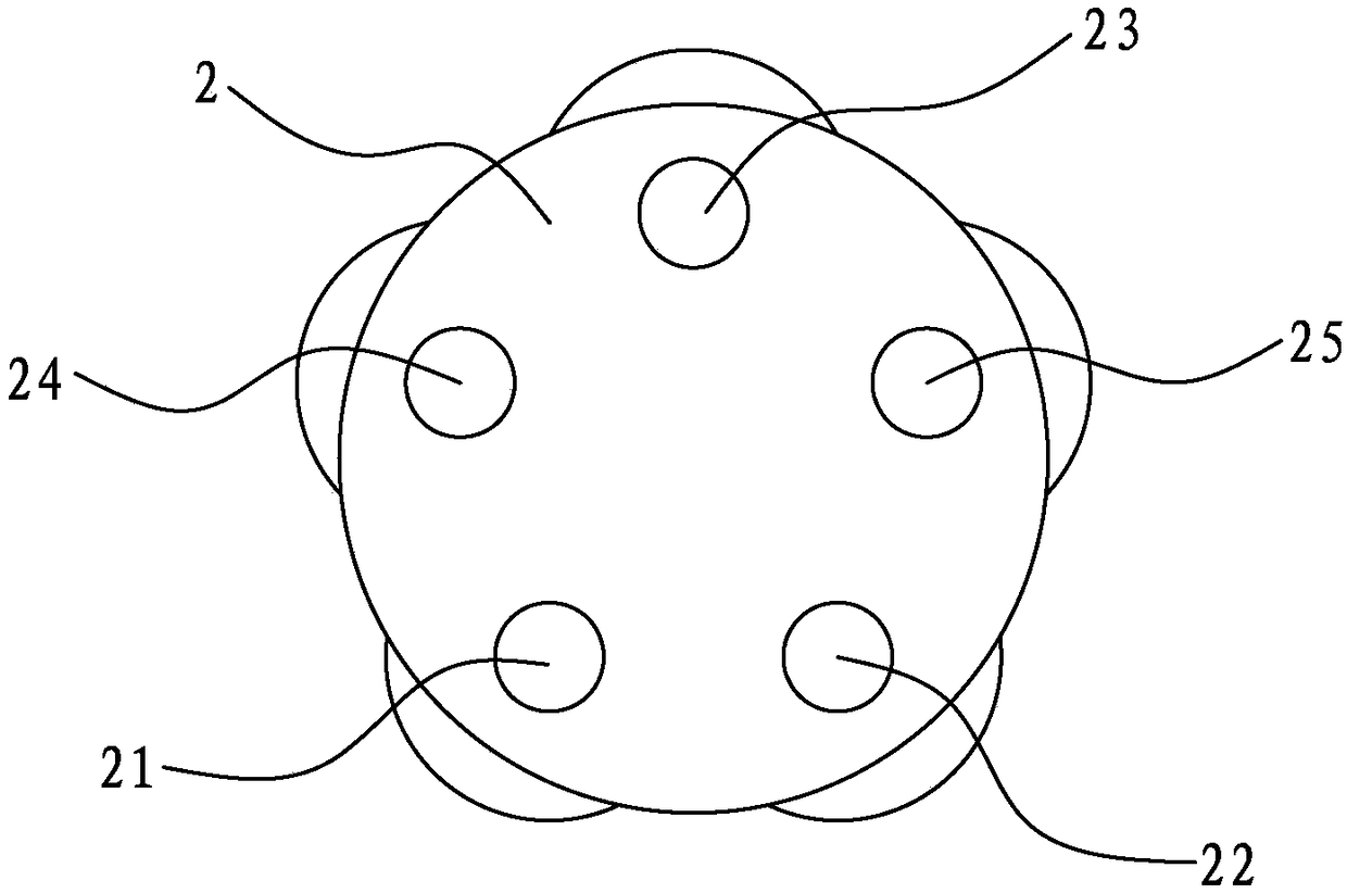
[0037] see Figure 1 to Figure 5 , the present invention discloses a valve body that can discharge small particles. The valve body 10 includes an upper cover 1, an upper valve core 2, a lower valve core 3, a casing 4 and a motor 5; the upper cover 1 is provided with The first port 13 and the second port 14, the upper valve core 2 is provided with a first hole 23 communicating with the first port 13 and a second hole 24 communicating with the second port 14, and the lower valve core 3 is provided with a Conducting or closing the water guide groove 31 of the first hole 23 and the second hole 24; the upper valve core 2 and the lower valve core 3 are attached together and assembled in the shell 4, and the upper cover 1 covers the shell 4, The lower spool 3 is connected to the motor 5 in rotation; the motor 5 drive...


PUM


Abstract

The invention discloses a valve body capable of discharging small particles and a liquid outlet device provided with the valve body. The valve body comprises an upper cover, an upper valve element, alower valve element, a shell and a motor. A first opening and a second opening are formed in the upper cover, a first hole communicating with the first opening and a second hole communicating with thesecond opening are formed in the upper valve element, and a water guide groove which can conduct or close the first hole and the second hole is formed in the lower valve element. The upper valve element and the lower valve element are attached together and assembled in the shell, the upper cover covers the shell, and the lower valve element is rotatably connected with the motor. The motor drivesthe lower valve element to rotate, and the water guide groove conduct or close the first hole and the second hole. The hole diameter of the first and second holes is greater than or equal to 2mm. Withthe structure, the hole diameter of the first and second holes of the valve body is greater than or equal to 2mm, the hole diameter of the first hole and the second hole is greater than that of a valve hole on an existing solenoid valve, the thick liquid containing the small particles, small powder or residues can be discharged smoothly, and the valve body is effectively prevented from being blocked.

Description

technical field [0001] The invention relates to a valve body structure, in particular to a valve body capable of discharging small particles and a liquid outlet device with the valve body. Background technique [0002] Existing coffee machines, soybean milk machines, fruit juice machines, beverage machines, washing machines, dishwashers, tea set washing machines, etc. produce liquids with small powders, small particles, thick, residues, etc.; however, the existing solenoid valves The valve hole of the solenoid valve is relatively small. When the liquid with particles is discharged, the valve hole will be blocked. Usually, a filter structure is installed at the third port of the solenoid valve to block the particles outside the filter structure, which is convenient for the solenoid valve to drain, and the particles are blocked. When blocked at the filter structure, the user needs to clean up these particles, and the workload increases. [0003] In view of this, the inventor ...

Claims


Application Information

Patent Timeline
Patent Type & Authority Applications(China)
IPC IPC(8): F16K11/074F16K31/04F16K27/04
CPCF16K11/074F16K27/045F16K31/041
Inventor 白斌将白家炫
Owner 白斌将
Learn More