

Control system for feeding grates
A control system and furnace technology, applied to incinerators, combustion methods, combustion types, etc., can solve the problems that the control system cannot correctly detect the position of the feeding grate, increase the labor intensity of operators, and easily interfere with sensor signals. Avoid easy interference and failure damage, reduce manual intervention, and simple operation and maintenance
Active Publication Date: 2018-12-18
EVERBRIGHT ENVIRONMENTAL PROTECTION TECH RES INST SHENZHEN CO LTD +2
View PDF5 Cites 0 Cited by
- Summary
- Abstract
- Description
- Claims
- Application Information
AI Technical Summary
Problems solved by technology
The working environment of the feeding grate is harsh, and the displacement pull rope sensor of the feeding grate often has failures such as wire rope breakage and zero position drift due to corrosion and other reasons, and the complex electromagnetic environment is easy to interfere with the sensor signal, resulting in the control system not being able to detect correctly The position of the feeding grate, even when the feeding grate runs to the end of the mechanical stroke, the feeding grate is stuck, and the feeding grate can
Method used
View moreImage
Smart ImageViewing Examples

Examples
 PUM
 Abstract
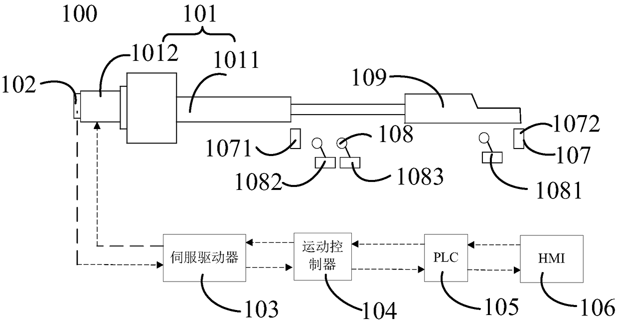
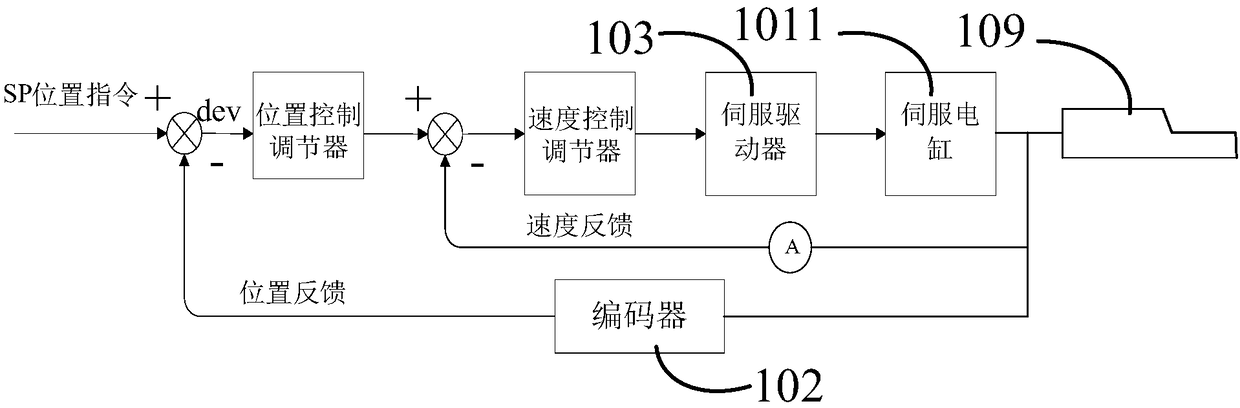
The invention provides a control system for feeding grates. The control system comprises a servo electric cylinder structure unit, an encoder, a servo driver, a motion controller, a programmable logiccontroller and a man-machine interface which are arranged in sequence. The servo electric cylinder structure unit comprises a servo electric cylinder and a servo motor, and the servo electric cylinder converts the rotational motion of the servo motor into the linear motion of the feeding grates. The encoder is used for measuring the angular displacement and angular velocity of the servo motor. The servo driver is used for controlling the motion of the servo motor. The motion controller is used for controlling the motion of the feed grates. The programmable logic controller and the man-machineinterface are used for writing a control program and an operation interface. According to the control system, the clean field environment can be maintained, energy is saved, noise is low, the energysaving and clean effects are achieved, impact resistance is high, and operation and maintenance are easy; the problems that interference is likely to occur and fault damages occur due to a displacement type pull rope sensor are avoided; and synchronous and asynchronous control of all the grates can be achieved.
Description
technical field [0001] The invention relates to the technical field of waste incineration, in particular to a control system for feeding grate. Background technique [0002] At present, with the development of urbanization, urban domestic waste is increasing day by day, and the traditional landfill method can no longer meet the demand. Waste incineration power generation has gradually become the main way of waste disposal. After modern incineration, the waste has been reduced. recycling, harmless and resourceful reuse. [0003] The garbage is poured into the chute from the feed port, and the garbage is sent to the hearth in the incinerator for incineration through the reciprocating push of the feeding grate. Feed grate in waste incineration is a very important equipment in the whole production. Its working stability and control mode affect the quality and sustainability of the whole incineration process, thus affecting the domestic waste treatment capacity and economic bene...
Claims
Login to View More Application Information
Patent Timeline
 IPC IPC(8): F23G5/50
CPCF23G5/50
Inventor李锋蔡曙光邵哲如王健生朱亮张二威洪益州钱中华杨应永
OwnerEVERBRIGHT ENVIRONMENTAL PROTECTION TECH RES INST SHENZHEN CO LTD