
Spacecraft high-precision angular motion measuring method based on rotor-type gyroscope biorthogonal configuration

A measurement method and technology of spacecraft, applied in directions such as integrated navigators, to achieve the effects of avoiding system noise, high-precision and high-dynamic measurement, and overcoming the contradiction between measurement accuracy and dynamic range

Inactive Publication Date: 2018-12-18
任元 +1
View PDF4 Cites 3 Cited by
  • Summary
  • Abstract
  • Description
  • Claims
  • Application Information

AI Technical Summary

Problems solved by technology

Although this method can improve the measurement or estimation accuracy of the attitude angular rate to a certain extent, there is inevitably a prominent contradiction between the detection accuracy and the detection dynamic range.

Method used


Image

  • Spacecraft high-precision angular motion measuring method based on rotor-type gyroscope biorthogonal configuration
  • Spacecraft high-precision angular motion measuring method based on rotor-type gyroscope biorthogonal configuration
  • Spacecraft high-precision angular motion measuring method based on rotor-type gyroscope biorthogonal configuration

Examples


Embodiment Construction

[0032] Specific implementation plan

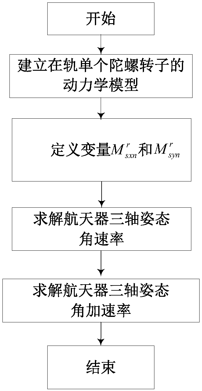
[0033] The specific embodiments of the present invention are as figure 1 As shown, the specific implementation steps are as follows:

[0034] (1) Establish a dynamic model of a single gyro rotor in orbit

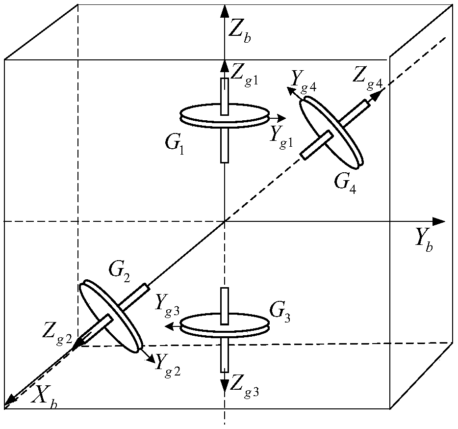
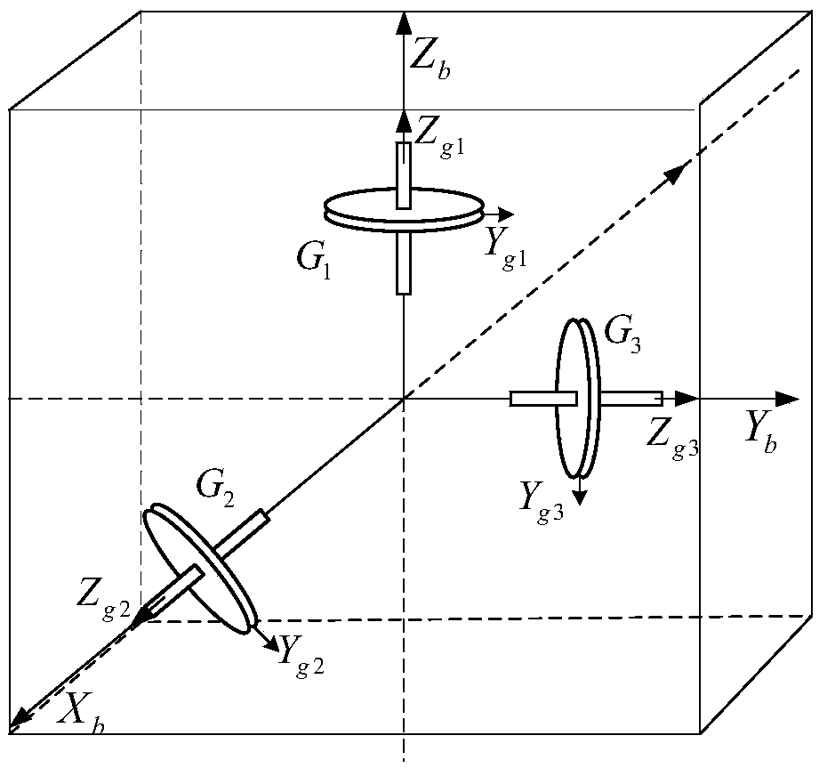
[0035] Such as figure 2 Shown, G 1 , G 2 , G 3 , G 4 4 rotor gyros, divided into two groups, G 1 And G 2 One set, G 3 And G 4 One group, the straight lines where the rotation axis of the two gyroscopes in each group point nominally are perpendicular to each other and coplanar in space; G between the two groups 1 And G 3 The two top rotating shafts are collinear in the straight line where they are nominally pointed, and the G between the two groups 2 And G 4 The straight lines where the nominal points of the two tops are located are also collinear, forming a "cross" configuration. Obviously this is a special form of the biorthogonal configuration; X b Y b Z b Is the satellite body coordinate system, G 1 And G 3 The nominal direction of the angu...


PUM


Abstract

The invention relates to a spacecraft high-precision angular motion measuring method based on rotor-type gyroscope biorthogonal configuration, and belongs to the technical filed of inertial navigation. An analytic relation including the posture angular rate and angular acceleration information of a spacecraft is obtained by utilizing resultant external moment radially borne by a gyroscope rotor, under the situation that an inertial coupling item and a cross coupling item caused by spacecraft angular motion are not neglected, the inertial coupling item and the cross coupling item are eliminatedthrough information fusion operation of a plurality of gyroscopes in the biorthogonal configuration, and thus the analytic relation including the angular rate and the angular acceleration of the spacecraft is obtained in a combined mode. Due to the fact that the inertial coupling item and the cross coupling item are reserved, the measuring precision of the spacecraft high-precision angular motionmeasuring method only depends on a gyroscope error and a configuration mounting error and is not lowered with increasing of the dynamic range of the spacecraft. According to the spacecraft high-precision angular motion measuring method, the prominent contradiction between the measuring precision and the dynamic range in a traditional posture angular rate and angular acceleration measuring methodis effectively overcome. The spacecraft high-precision angular motion measuring method can be applied to high-precision and high-bandwidth measuring of the angular rate and the angular acceleration ofthe spacecraft.

Description

Technical field [0001] The invention relates to a spacecraft high-precision angular motion measurement method based on a rotor-type gyro biorthogonal configuration, which is suitable for the occasion where the rotor-type gyro configuration is used as the spacecraft attitude angle motion information measurement. technical background [0002] Rotor gyroscopes mainly include flexible gyroscopes, maglev gyroscopes, liquid float gyroscopes, electrostatic gyroscopes, three-float gyroscopes, and two-float gyroscopes. Because of their high measurement accuracy, they are the first choice for current high-precision inertial navigation systems. Rotor-type gyroscopes usually have one or two degrees of freedom angular rate sensitivity. Using three gyroscopes to be installed orthogonally to each other to achieve spacecraft three-axis attitude angular rate measurement is a common installation method for inertial navigation systems. In this installation method and solution method, in order to ac...

Claims


Application Information

Patent Timeline
Patent Type & Authority Applications(China)
IPC IPC(8): G01C21/24
CPCG01C21/24
Inventor 陈晓岑任元樊亚洪王丽芬蔡远文王卫杰陈琳琳吴昊满万鑫
Owner 任元
Learn More