
Soil taking device for engineering investigation

A soil-taking device and engineering survey technology, applied in the direction of sampling devices, etc., can solve the problems of laborious operation, waste of manpower, troublesome operation, etc., and achieve the effects of convenient use, improved work efficiency, and simple structure

Inactive Publication Date: 2018-12-18
章庆
View PDF5 Cites 1 Cited by
  • Summary
  • Abstract
  • Description
  • Claims
  • Application Information

AI Technical Summary

Problems solved by technology

[0004] The earth-taking device proposed in this patent needs to be manually turned to handle the handle, which is cumbersome to operate and wastes manpower, and when encountering a relatively hard soil layer, the manpower operation is laborious and the work efficiency is low

Method used


Image

  • Soil taking device for engineering investigation
  • Soil taking device for engineering investigation

Examples


Embodiment Construction

[0019] The following will clearly and completely describe the technical solutions in the embodiments of the present invention with reference to the accompanying drawings in the embodiments of the present invention. Obviously, the described embodiments are only some of the embodiments of the present invention, not all of them.

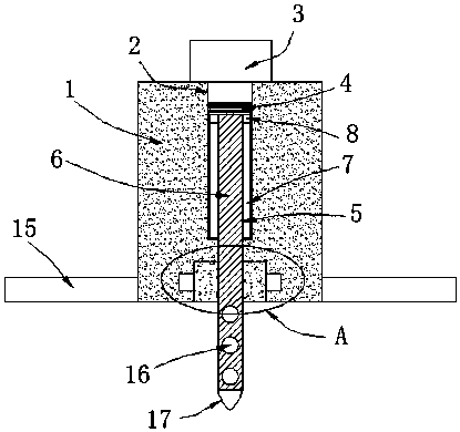
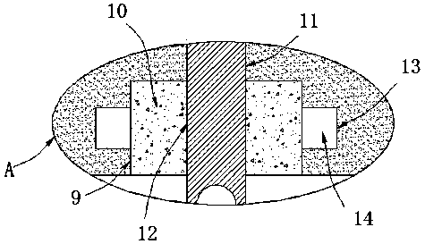
[0020] refer to Figure 1-2 , a soil fetching device for engineering survey, comprising a fixed block 1, the top of the fixed block 1 is provided with a rotating groove 2, the top of the fixed block 1 is fixedly installed with a driving motor 3, and the output shaft of the driving motor 3 extends to the rotating groove 2 The rotating rod 4 is welded inside, the bottom of the rotating rod 4 is provided with a chute 5, the screw rod 6 is slidably installed in the chute 5, the bottom of the fixed block 1 is provided with a placement groove 9, and a threaded block is fixedly installed in the placement groove 9 10. A threaded hole 12 is provided on the threa...


PUM


Abstract

The invention discloses a soil taking device for engineering investigation, which comprises a fixed block. A rotating groove is formed at the top of the fixed block; a driving motor is fixedly mountedat the top of the fixed block; an output shaft of the driving motor extends into the rotating groove and is welded with a rotating rod; a chute is formed at the bottom of the rotating rod; a screw rod is mounted in a sliding mode in the chute; a placement groove is formed at the bottom of the fixed block; a threaded block is fixed mounted in the placement groove; a threaded hole is formed on thethreaded block; a rotating hole is formed on the inner wall of the top of the placement groove; the rotating hole is communicated with the rotating groove; the bottom of the screw rod runs through therotating hole to extend into the placement groove and is in threaded connection with the threaded hole; limiting grooves are formed on the inner walls of both sides of the chute; the tops of both sides of the screw rod are welded with limiting blocks; and two limiting blocks are respectively matched with two limiting grooves. The soil taking device can automatically carry out rotation and drilling on a drill bit, improves working efficiency and is simple in structure and convenient to use.

Description

technical field [0001] The invention relates to the technical field of soil-taking devices, in particular to a soil-taking device for engineering survey. Background technique [0002] Among the existing engineering investigation equipment, the soil fetching device is an important tool, which can help the staff to carry out soil research. [0003] After searching, the patent document with the application number 201721882840.0 discloses a soil-taking device for engineering survey, including a grip rod, a connecting rod, a cylinder, a pedal and a drill bit, and the bottom of the grip rod and the connecting rod are fixedly connected by welding , the connecting rod is arranged inside the cylinder body, both sides of the inner wall of the middle end of the cylinder body are provided with threaded blocks, both sides of the middle part of the connecting rod are provided with threads, and the connecting rod is connected with the threaded blocks through threads, so The upper end of t...

Claims


Application Information

Patent Timeline
Patent Type & Authority Applications(China)
IPC IPC(8): G01N1/08
CPCG01N1/08
Inventor 章庆
Owner 章庆
Learn More