Liquid lens capable of realizing electronic control focusing

A liquid lens, focusing technology, used in lenses, optics, instruments, etc., can solve problems such as increasing complexity and cost

Active Publication Date: 2018-12-18
CHINA JILIANG UNIV
View PDF8 Cites 11 Cited by
  • Summary
  • Abstract
  • Description
  • Claims
  • Application Information

AI Technical Summary

Problems solved by technology

However, this liquid lens is composed of two liquids, and the focal length is changed by ch

Method used


Image

  • Liquid lens capable of realizing electronic control focusing
  • Liquid lens capable of realizing electronic control focusing
  • Liquid lens capable of realizing electronic control focusing

Examples


Embodiment Construction

[0038] In order to illustrate the specific flow of the present invention, the following will be described in detail in conjunction with the accompanying drawings.

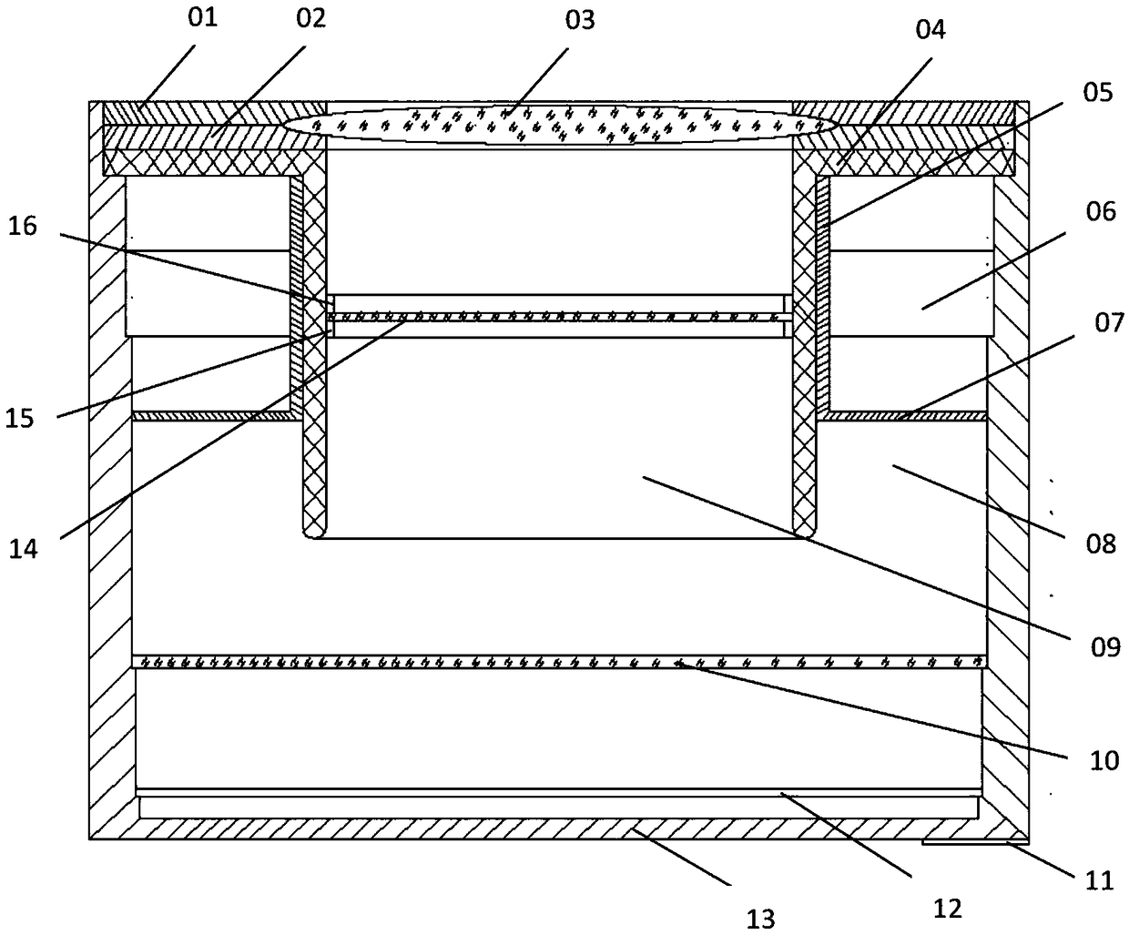
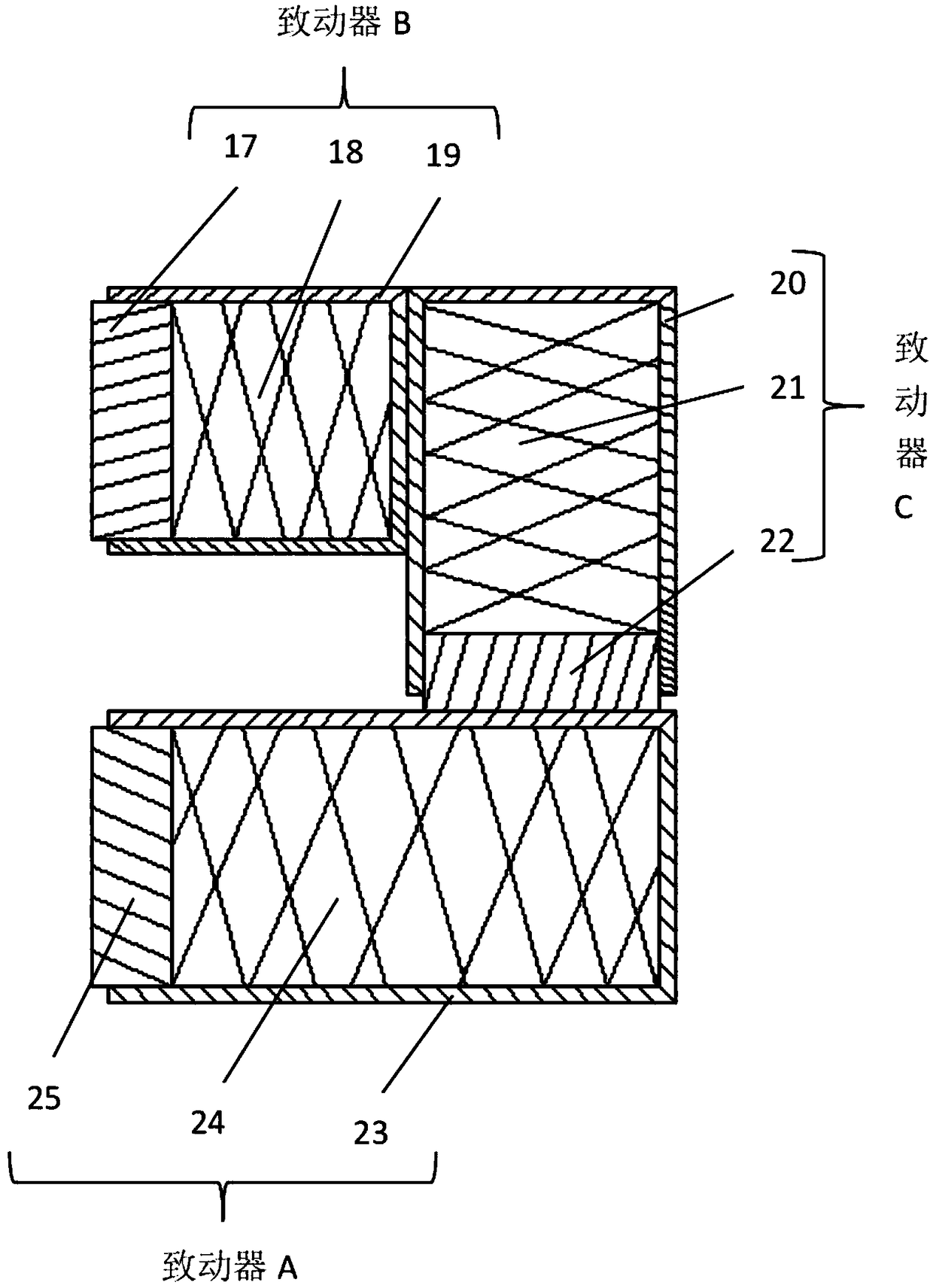
[0039] refer to figure 1 , an electronically controlled focusing liquid lens. The electronically controlled focusing liquid lens in the present invention includes: 01 lens fixing ring 1, 02 lens fixing ring 2, 03 lens window 1, 04 piezoelectric ceramic tube, 05 linear guide rail, 06 piezoelectric actuator, 07 pushing pressure film, 08 actuating cavity, 09 liquid cavity, 10 lens window 2, 11 lens external interface, 12 vision sensor, 13 lens housing, 14 sealing lens, 15 sealing ring 1, 16 sealing ring 2, 17 driving foot B, 18 pressure Electric ceramic stack B, 19 Actuator B shell, 20 Actuator C shell, 21 Piezoelectric ceramic stack C, 22 Drive foot C, 23 Actuator A shell, 24 Piezoelectric ceramic stack A, 25 Driver Foot A.

[0040] The lens fixing ring 1 (01) and the lens fixing ring 2 (02) are connected with the...


PUM


Abstract

The present invention discloses a liquid lens capable of realizing electronic control focusing. The liquid lens comprises: a first lens fixing ring (01), a second fixing ring (02), a first lens window(03), a piezoelectric ceramic tube (04), a straight-line guiding rail (05), a piezoelectric actuator (06), a pushing pressing piece (07), an actuating cavity (08), a liquid cavity (09), a second lenswindow (10), a lens external interface (11), a vision sensor (12), a lens shell (13), a sealed lens (14), a first sealing ring (15), a second sealing ring (16), a driving foot B (17), a piezoelectricceramic stack B (18), a actuator B shell (19), a actuator C shell (20), a piezoelectric ceramic stack C (21), a driving foot C (22), a actuator A shell (23), a piezoelectric ceramic stack A (24) anda driving foot A (25). According to the liquid lens, by applying a sinusoidal alternating current voltage signal on an internal electrode and an external electrode of the piezoelectric ceramic tube (04), a radial ultrasound field is generated in the piezoelectric ceramic tube (04), so that the internal liquid refractive index is changed, and thus focal length of the liquid lens is changed. By controlling the piezoelectric actuator (06), the liquid height in the liquid cavity (09) is changed, and thus the imaging size of objects is changed. The liquid lens capable of realizing the electronic control focusing has the advantages of convenient and simple manufacture, wide application range and strong practicability.

Description

technical field [0001] The invention relates to an electrically controlled focusing liquid lens. Background technique [0002] According to different working principles and structures, the current liquid lenses can be divided into three categories: (1) double liquid lenses based on the principle of electrowetting; (2) single liquid lenses that change the shape and volume of the lens through mechanical force; (3) A liquid crystal lens that changes the alignment state of liquid crystal molecules by applying electricity to cause a change in the refractive index. [0003] Since the liquid lens does not require mechanical movement, the liquid lens has the advantages of small size, convenient operation, and easy integration compared with the previous lens that uses mechanical movement to adjust the focus. So it is widely used. The current mainstream liquid lens is a variable-focus lens based on the phenomenon of electrowetting, in which electrodes coated with a special insulatin...

Claims


Application Information

Patent Timeline
IPC IPC(8): G02B3/14G02B26/00
CPCG02B3/14G02B26/004
Inventor 吴羽峰金尚忠金怀洲王赟方维陈亮
Owner CHINA JILIANG UNIV
Why Eureka
Try Eureka