

Chip strip counting device and method based on photoelectric detection
A technology of photoelectric detection and counting devices, applied in the direction of counting mechanisms/items, instruments, etc., can solve the problems of large-scale equipment cost and portability, and achieve the effects of solving cost and portability, easy operation, solving efficiency and accuracy
- Summary
- Abstract
- Description
- Claims
- Application Information
AI Technical Summary
Problems solved by technology
Method used
Image

Examples
Embodiment 1
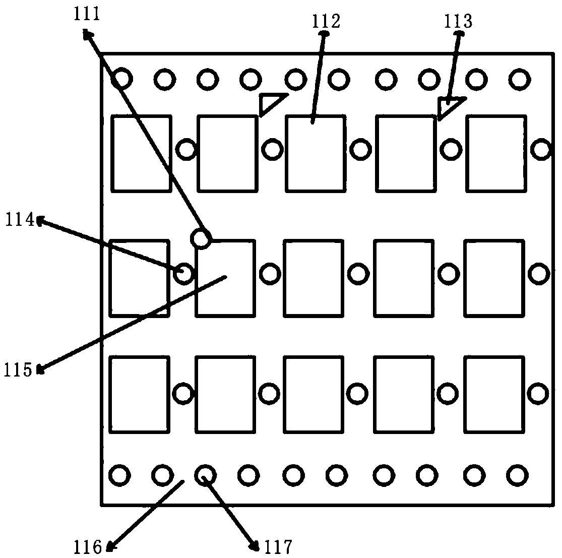
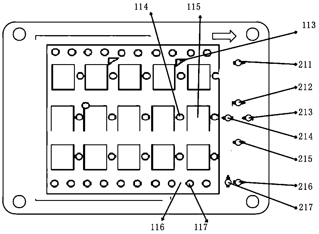
[0024] This embodiment discloses a chip strip counting device based on photoelectric detection, such as figure 1 As shown, the strip is a non-contact strip, the chip strip is loaded with 3 rows and 5 columns of 15 chips, a damage identification hole 111 is punched on the fixed corner of the damaged chip, and the center of the chip strip is provided with multiple chips. A central positioning hole 114, each central positioning hole 114 is located at the front end of each row of chips, and side positioning holes 117 are opened on both sides of the chip strip. In order to make the positioning more accurate when counting and detecting, a central auxiliary positioning point 115 is provided on the chip adjacent to the central positioning hole 114, and a side auxiliary positioning point 116 is provided between the side positioning holes 117, and the central auxiliary positioning point 115 is set. In the light-shielding layer on the chip, the side auxiliary positioning point 116 is a l...
Embodiment 2
[0034] A device for counting contact chip strips is disclosed in this embodiment, such as Figure 5 As shown, it is a schematic diagram of the structure of the contact strip; the difference between it and the non-contact chip strip is mainly the difference in loading chips, and the chip loaded on the non-contact strip is mainly used for non-contact cards such as bus cards, etc. The chip is mainly used for card chips used in card insertion equipment, such as bank cards and mobile phone cards.
[0035] The contact chip strip described in this implementation includes a total of 6 chips in 2 rows and 3 columns. The damaged chips are provided with damage identification holes 411, 412, and the center of the strip is provided with a central positioning hole 44 in the middle of the two rows of chips. Side positioning holes 43 are provided on both sides of the strip. Compared with the non-contact strip described in Embodiment 1, there are no central auxiliary positioning points and sid...
Embodiment 3
[0038] This embodiment discloses a method for counting chip stripes based on photoelectric detection, which includes the following steps:
[0039] S01), process the chip strip to be tested with M rows and N columns of chips, M and N are positive integers, punch a damage identification hole on the fixed corner of the damaged chip, and punch a hole in each column in the center of the chip strip A central positioning hole is opened on the front end of the chip, and multiple side positioning holes are opened on both sides of the chip strip;
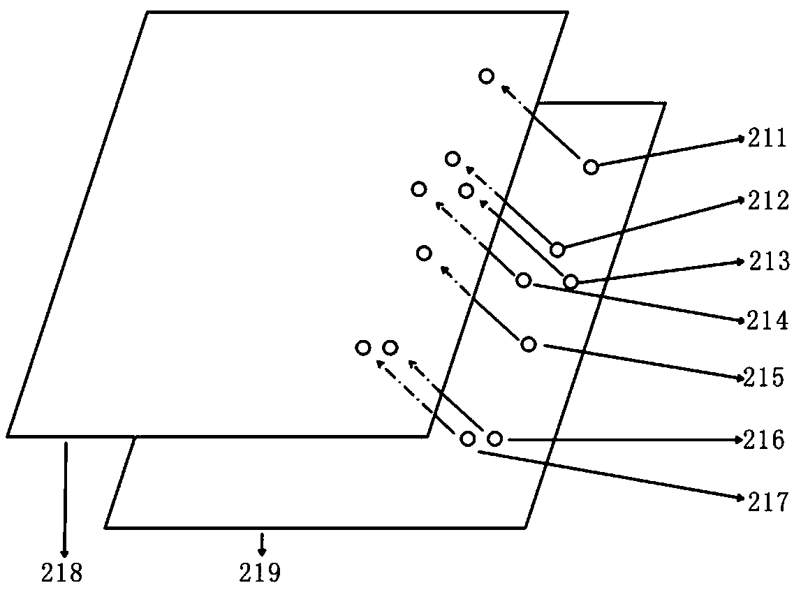
[0040] S02), setting up the upper detection board and the lower detection board, first make the upper detection board and the lower detection board parallel and leave a space between the upper and lower detection boards for the chip strips to pass through, and then place the upper detection board and the lower detection board Multiple pairs of photoelectric detection points are set on the top, and the photoelectric detection points include pu...
PUM
 Abstract
Description
Claims
Application Information