A multi-exposure image fusion method for halo removal

An image fusion and multi-exposure technology, applied in the field of image processing, can solve the problems of the halo phenomenon caused by the fusion image, affecting the visual perception results of the human eye, and the halo phenomenon.

Active Publication Date: 2018-12-18
NINGBO UNIV
View PDF5 Cites 10 Cited by
  • Summary
  • Abstract
  • Description
  • Claims
  • Application Information

AI Technical Summary

Problems solved by technology

However, the above fusion methods do not fully consider the high dynamic range scene. The high dynamic range image obtained by multi-exposure fusion is likely to produce halo phenomenon in the local brightness change area, which affects the human visual perception result.
In the process of multi-exposure image fusion, halo phenomenon will occur in the area where the brightness changes sharply in the scene. The main reason is that during the acquisition process of the multi-exposure image sequence, a certain dynamic range of the scene can be obtained by changing the exposure and choosing the brightness information. However, the degree of severe local brightness changes in the scene may far exceed the dynamic range that ordinary cameras can cover. The gradient amplitude obtained at the adjacent boundary is much larger than the gradient amplitude obtained at the same position under other exposure conditions. Applying this large value gradient to the multi-exposure fusion process will produce halos in the fused image

Method used


Image

  • A multi-exposure image fusion method for halo removal
  • A multi-exposure image fusion method for halo removal
  • A multi-exposure image fusion method for halo removal

Examples


Embodiment Construction

[0049] The present invention will be further described in detail below in conjunction with the accompanying drawings and embodiments.

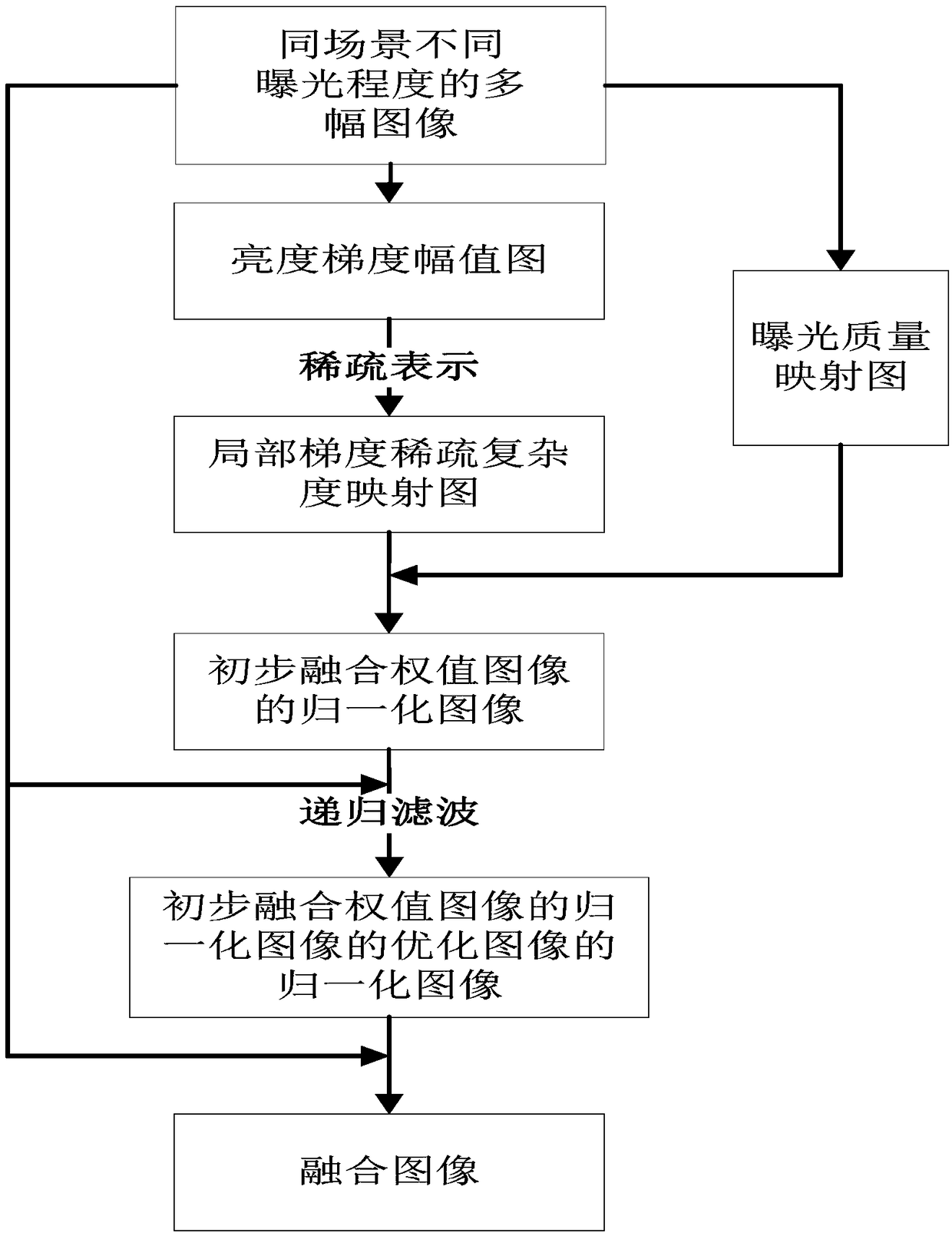
[0050] Since there are drastic local brightness changes in high dynamic range scenes, which may far exceed the dynamic range covered by ordinary cameras, the multi-exposure image sequence obtained by gradually changing the exposure parameters will be in a region with severe local brightness changes under a certain exposure condition. There is a phenomenon that overexposure and underexposure are adjacent, and the gradient amplitude obtained at the adjacent boundary under this exposure condition is much larger than the gradient amplitude obtained at the same position under other exposure conditions. If the intensity of the gradient amplitude is used as the basis for image fusion, halo phenomenon will be generated in the invalid gradient neighborhood with large amplitude. Therefore, it can be considered that the large-value gradient is an invalid...


PUM


Abstract

The invention discloses a multi-exposure image fusion method for halo removal, which calculates a local gradient sparse complexity map and an exposure quality map of a brightness image of each exposure image. Then, the preliminary fusion weight image of brightness images of each exposure image are obtained through fusion, and the normalized image of the optimized image of the normalized image of the preliminary fusion weight image of the brightness image of each exposure image is obtained. The final fusion image of all the exposure images is obtained. The invention has the advantages that thelocal gradient sparse complexity mapping map and the exposure quality mapping map are constructed for image fusion according to the sparse representation of the gradient magnitude image of the luminance image, the influence of the invalid gradient of the large magnitude in the image fusion process is effectively suppressed, the halo phenomenon in the fusion image is eliminated, and the texture details of the image under different exposure conditions in the multi-exposure image sequence can be extracted more effectively, so that the fusion image contains more texture details and has higher definition.

Description

technical field [0001] The invention relates to an image processing technology, in particular to a multi-exposure image fusion method for halo removal. Background technique [0002] Dynamic range is the ratio of the maximum and minimum values ​​in a signal that can vary. For an actual scene, the dynamic range refers to the ratio of the maximum brightness value to the minimum brightness value existing in the actual scene. Due to the rich light, shadow and color information in the real natural environment, the dynamic range of its brightness is generally very large, and the maximum can span 10 14 The order of magnitude far exceeds the dynamic range that can be captured by common imaging devices currently on the market. Therefore, the high dynamic range imaging technology that can truly reproduce natural scenes has become more and more popular due to its perfect texture detail preservation and realistic visual perception. Widely used in digital photography, aerospace, satelli...

Claims


Application Information

Patent Timeline
Patent Type & Authority Applications(China)
IPC IPC(8): G06T5/00G06T5/50
CPCG06T5/007G06T5/50
Inventor 郁梅邵华蒋刚毅宋洋姜浩彭宗举陈芬
Owner NINGBO UNIV
Why Eureka
Try Eureka