

Transformer Inductance Adjustment Method for Aviation Ignition Device
An ignition device and inductance adjustment technology, which is applied in the direction of transformers, variable inductors, variable transformers, etc., can solve the problems of adjusting inductance, position, and size of transformer coils, and can not be adjusted, so as to achieve convenient adjustment and ensure use reliability effect
- Summary
- Abstract
- Description
- Claims
- Application Information
AI Technical Summary
Problems solved by technology
Method used
Image

Examples
Embodiment
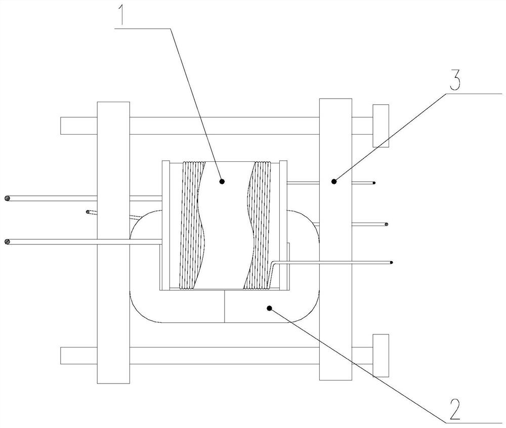
[0021] Some kind of aviation ignition transformer, its iron core is made of U-shaped iron core pressed by multiple thin silicon steel strips with a thickness of 0.08mm, and the inductance of the transformer after assembly is required to be 300±20μH. The specific installation The adjustment method is as follows:
[0022] 1) Preparation: Prepare qualified coil components, U-shaped iron cores and parallel clips, and use silk cloth to dip anhydrous ethanol to clean the 2 end faces of the U-shaped iron core to ensure that they are clean and free of impurities.
[0023] 2) Assembly: Insert one end of the two U-shaped iron cores into the center hole of the skeleton of the coil component, and then put them into the parallel clamp as a whole, align the end faces of the iron cores, and tighten the parallel clamp screws to ensure that the two halves of the iron cores are docked neatly;
[0024] 3) Measurement: Set up the LCR measuring instrument, and set the test conditions as 1kHz, 1.0V...
PUM
| Property | Measurement | Unit |
|---|---|---|
| thickness | aaaaa | aaaaa |
| inductance | aaaaa | aaaaa |
| inductance | aaaaa | aaaaa |
Abstract
Description
Claims
Application Information