A High Efficiency Integrated llc Resonant Transformer

A resonant transformer and integrated technology, which is applied in the field of power electronics technology and its application, can solve the problems of weakening the advantages of high efficiency of LLC resonant converter, the decrease of transformer conversion efficiency, and the difficulty of magnetic integration of resonance parameters, etc., and achieve the reduction of proximity effect, The effect of increasing the magnetic path length and weakening the influence

Active Publication Date: 2020-11-06
HUNAN INSTITUTE OF ENGINEERING
View PDF1 Cites 0 Cited by
  • Summary
  • Abstract
  • Description
  • Claims
  • Application Information

AI Technical Summary

Problems solved by technology

The disadvantages of the traditional solution are: the magnetic field around the air gap will produce edge efficiency on the nearby windings or conductors, causing large losses; the double-slot structure causes the window length to be halved, the window utilization rate is reduced, and the number of turns of each layer of winding is reduced. The number of layers in the winding increases, so the proximity effect is significant and the AC resistance loss increases
These shortcomings are more obvious in high-power applications, resulting in difficulties in the magnetic integration of resonance parameters in high-power applications, and the reduction of transformer conversion efficiency, which weakens the advantages of high efficiency of LLC resonant converters.

Method used


Image

  • A High Efficiency Integrated llc Resonant Transformer
  • A High Efficiency Integrated llc Resonant Transformer
  • A High Efficiency Integrated llc Resonant Transformer

Examples


Embodiment Construction

[0047] The following will clearly and completely describe the technical solutions in the embodiments of the present invention with reference to the accompanying drawings in the embodiments of the present invention. Obviously, the described embodiments are only some, not all, embodiments of the present invention. Based on the embodiments of the present invention, all other embodiments obtained by persons of ordinary skill in the art without making creative efforts belong to the protection scope of the present invention.

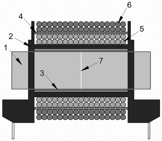
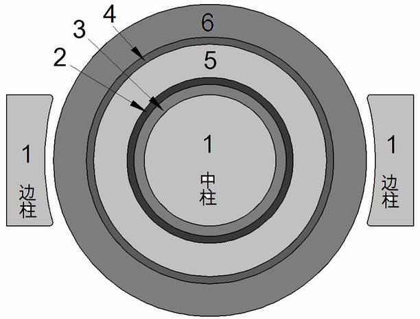
[0048] The purpose of the present invention is to provide a high-efficiency integrated LLC resonant transformer, which can integrate the resonant inductance and magnetizing inductance required for LLC resonant conversion inside the transformer, while overcoming the shortcomings of traditional LLC resonant transformers, realizing whether it is in small or medium power It can also achieve the purpose of high-efficiency energy transfer under high-power application...


PUM


Abstract

The invention discloses a high-efficiency integrated LLC resonant transformer. The transformer comprises a magnetic core 1, a framework 2, a magnetic layer of low magnetic permeability 3, a magnetic layer of low magnetic permeability 4, a primary winding 5, a secondary winding 6 and an air gap 7. The air gap 7 is located in the middle column of the magnetic core 1; the magnetic layer of low magnetic permeability 3 tightly wraps the middle column of the magnetic core 1; the primary winding winds around inside the inner layer; the secondary winding winds around the outer layer; the magnetic layer of low magnetic permeability 4 is located between the primary winding 5 and the secondary winding 6. The high-efficiency integrated LLC resonant transformer solves the defects that a traditional LLCresonant transformer is difficult to integrate in a high-power application and the efficiency is reduced, and is capable of not only integrating the resonant inductor and the excitation inductor required by the LLC resonant converter into the transformer, but also reducing the edge effect and the adjacent effect of the transformer, effectively improving the energy transfer efficiency of the transformer.

Description

technical field [0001] The invention relates to the field of power electronics technology and its application, in particular to a high-efficiency integrated transformer applied to an LLC resonant converter. Background technique [0002] As an excellent switching power supply topology with high efficiency, high power density and low EMI, the LLC resonant converter has attracted the attention of scholars and engineers, and has been widely used in communication power supplies, LED power supplies, and electric vehicle charging power supplies. application. LLC resonant transformer, as the core device in LLC resonant converter, is very important to the efficiency, power density and reliability of the circuit. The traditional LLC resonant transformer scheme generally adopts a double-slot skeleton, the primary winding and the secondary winding are respectively wound in two slots, isolated from each other, and there is a large leakage flux, which is used to realize the resonance of ...

Claims


Application Information

Patent Timeline
IPC IPC(8): H01F3/14H01F27/30H01F38/00
CPCH01F3/14H01F27/306H01F38/00H01F2017/0066
Inventor 赵振兴易炜溟
Owner HUNAN INSTITUTE OF ENGINEERING
Why Eureka
Try Eureka