Supercharge Your Innovation With Domain-Expert AI Agents!

A LED light line splitting connection mount assembly

A technology of LED lighting and split-line connection, which is applied in the direction of line/collector parts, connection, conductive connection, etc., can solve the problems that affect the overall line layout aesthetics and conductive effect, low connection strength, time-consuming and labor-intensive, etc. Achieve the effect of improving the appearance quality of the wiring, improving the conductive effect, and reducing the electrical loss

Inactive Publication Date: 2018-12-18
濉溪淮匠机械设备有限责任公司
View PDF7 Cites 0 Cited by
  • Summary
  • Abstract
  • Description
  • Claims
  • Application Information

AI Technical Summary

Problems solved by technology

[0002] Ordinary lighting lines are generally single-wire connections. The connection and installation process is to manually overlap two wires and twist them into threaded shapes, and then wrap insulating tape on the surface to complete the installation; while in the process of laying LED lighting lines, due to LED Many lamps are connected in series, so it is often necessary to install separate lines, that is, one main line needs to be connected to two auxiliary lines. Low, affecting the layout aesthetics and conductive effect of the overall line, therefore, it is necessary to design a special branch line connection method and tool to improve the connection installation efficiency and overall effect of the branch line

Method used


Image

  • A LED light line splitting connection mount assembly
  • A LED light line splitting connection mount assembly
  • A LED light line splitting connection mount assembly

Examples


Embodiment Construction

[0022] The present invention will be described in detail below in conjunction with the accompanying drawings.

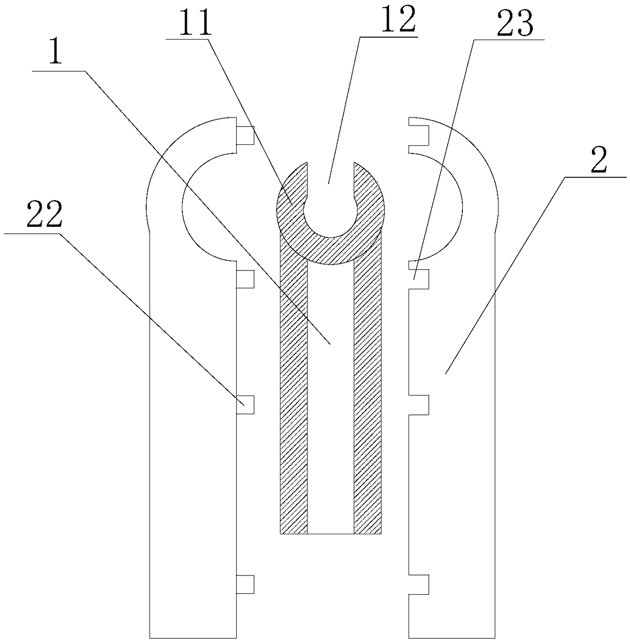
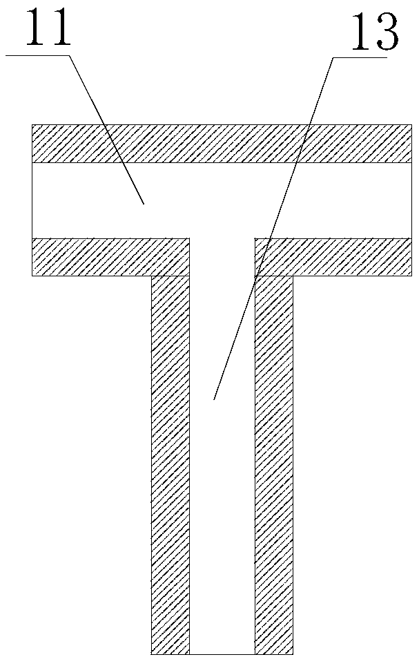
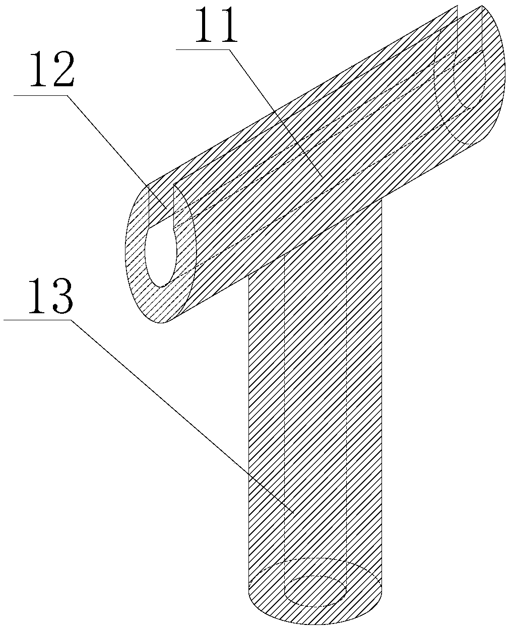
[0023] Such as Figure 1-8 As shown, a LED lighting line branching connection installation assembly includes a branching connection terminal and wiring pliers; the branching connection terminal includes a conductive connecting tube 1 and an insulating protective sleeve, and the conductive connecting tube 1 is a T-shaped tee Pipe structure, the upper wall of the horizontal pipe 11 of the conductive connecting pipe 1 has a radial opening 12 along the center of the pipe wall, and the width of the opening 12 is slightly smaller than the inner diameter of the horizontal pipe 11; T-shaped insulating sheet 2, the length of the T-shaped insulating sheet 2 is slightly longer than the length of the conductive connecting pipe 1, grooves 21 are symmetrically opened on the inner side walls of the two insulating sheets 2, and the grooves 21 and the The outer wall of the conductiv...


PUM


Abstract

The invention discloses an LED lighting line splitting connection mounting assembly, which comprises a splitting connection terminal and a wiring clamp. The branch line connection terminal comprises aconductive connection pipe and an insulating protective sleeve, wherein the conductive connection pipe is a T-shaped three-way pipe structure; the upper wall of the horizontal pipe of the conductiveconnection pipe is radially opened along the center of the pipe wall, and the width of the opening is slightly smaller than the inner diameter of the horizontal pipe; The insulating protective sleevecomprises two mutually engaged T-shaped insulating sheets, wherein the length of the T-shaped insulating sheets is slightly larger than the length of the conductive connecting pipe, and a groove is symmetrically provided on the inner side walls of the two insulating sheets, and the groove corresponds to the outer wall of the conductive connecting pipe, so that the insulating protective sleeve is completely wrapped on the outer wall of the conductive connecting pipe; The wiring connector tong comprises a tong nozzle and a handle, wherein the front part of the tong nozzle is provided with a thread cutting knife edge, the middle part of the tong nozzle is provided with a compression concave hole, the compression concave hole is an elliptical hole, inverted teeth are arranged on the inner wallof the compression concave hole, and the rear part of the tong nozzle is hingedly connected with the handle through a pin shaft.

Description

technical field [0001] The invention relates to a wire and cable connection device, in particular to a wire and cable branch connection installation assembly for LED lighting circuits. Background technique [0002] Ordinary lighting lines are generally single-wire connections. The connection and installation process is to manually overlap two wires and twist them into a threaded shape, and then wrap insulating tape on the surface to complete the installation; and in the process of laying LED lighting lines, due to LED Many lamps are connected in series, so it is often necessary to install separate lines, that is, one main line needs to be connected to two auxiliary lines. Therefore, it is necessary to design a special branch line connection method and tool to improve the connection installation efficiency and overall effect of the branch line. Contents of the invention [0003] Aiming at the technical problem, the present invention proposes a simple-structured and easy-to...

Claims


Application Information

Patent Timeline
IPC IPC(8): H01R4/20H01R11/01H01R11/09H01R43/042
CPCH01R11/01H01R4/20H01R11/09H01R43/042
Inventor 丁言虎许乃馨谢宏欣刘光辉陈雷张鹏
Owner 濉溪淮匠机械设备有限责任公司
Features
  • R&D
  • Intellectual Property
  • Life Sciences
  • Materials
  • Tech Scout
  • Unparalleled Data Quality
  • Higher Quality Content
  • 60% Fewer Hallucinations
Learn More