A new type of cable bridge

A cable bridge, a new type of technology, applied in the direction of electrical components, etc., can solve the problems of large traction force, large friction force, and cable winding, etc., to achieve the effect of reducing traction force, small friction force, and avoiding fuzzing

Inactive Publication Date: 2018-12-18
镇江苏电电气有限公司
View PDF0 Cites 0 Cited by
  • Summary
  • Abstract
  • Description
  • Claims
  • Application Information

AI Technical Summary

Problems solved by technology

Existing cable trays generally place multiple cables. When one of them fails, it will be difficult to pull out because the cables will be entangled together.
In addition, when the cable is pulled, the contact area between the cable and the bottom plate of the bridge frame is large, and the friction force is also large, so a large traction force is required, and the protective layer of the cable is easy to pull, causing a safety hazard

Method used


Image

  • A new type of cable bridge

Examples


Embodiment Construction

[0013] The present invention will be further described below in conjunction with the accompanying drawings. The following examples are only used to illustrate the technical solution of the present invention more clearly, but not to limit the protection scope of the present invention.

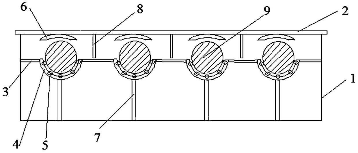
[0014] like figure 1 As shown, a new type of cable tray includes a main body 1 and a cover plate 2. The inner walls on both sides of the main body 1 are connected with load-bearing plates 3. The load-bearing plate 3 is provided with several concave plates 4 along the width direction of the bridge. Inside the concave plates 4 Inlaid with balls 5, the lower end of the concave plate 4 is connected to the upper end of the support rod 7, the lower end of the support rod 7 is arranged on the bottom plate of the main body part 1, the concave plate 4 is used to accommodate the lower part of the cable 9, and the lower surface of the cover plate 2 is connected. There is a buckle part 6, and the buckle par...


PUM


Abstract

The invention discloses a novel cable bridge, includes a main body part and a cover plate, A load-bearing plate (3) is connecte to that inner wall of both sides of the main body part (1), the bearingplate (3) is provided with a plurality of concave plates (4) along the width direction of the bridge frame, A ball (5) is embedded in the concave plate (4), the lower end of the concave plate (4) is connected with the upper end of the support rod (7), A low end of that support bar (7) is arranged on the bottom plate of the main body part (1), The concave plate (4) is used for accommodating the lower part of the cable (9), the lower surface of the cover plate (2) is connected with a clasp part (6), the clasp part (6) is used for limiting the upper end of the cable (9), a partition plate (8) isarranged between two connected clasp parts (6), and the upper end of the partition plate (8) is connected with the lower surface of the cover plate (2). The invention relates to a novel cable bridge,wherein the cable is separated and placed and the cable is easy to be pulled out.

Description

technical field [0001] The invention relates to a novel cable bridge, which belongs to the field of electrical equipment. Background technique [0002] As a common support and protection device for cable laying in the electrical equipment power supply system, the cable tray protects and guides the cables laid in the cable tray. Traditional cable trays are mainly divided into trough, ladder, tray and grid structures. Existing cable trays generally place multiple cables, and when one of them fails, it will be difficult to pull out because the cables will be contacted and entangled. In addition, when the cable is pulled, the contact area between the cable and the bottom plate of the bridge frame is large, and the friction force is also large, so a large traction force is required, and the protective layer of the cable is easy to pull, causing a safety hazard. Contents of the invention [0003] The technical problem to be solved by the present invention is to provide a new t...

Claims


Application Information

Patent Timeline
Patent Type & Authority Applications(China)
IPC IPC(8): H02G3/04
CPCH02G3/0406
Inventor 宋振达
Owner 镇江苏电电气有限公司
Why Eureka
Try Eureka