Jitter correction method and jitter correction apparatus

A technology of shake correction and equipment, applied in the field of anti-shake, can solve the problem that the accuracy of small shake correction is difficult to meet the requirements, and achieve the effect of flexible shake correction and high precision

Active Publication Date: 2018-12-18
RICOH KK
View PDF6 Cites 4 Cited by
  • Summary
  • Abstract
  • Description
  • Claims
  • Application Information

AI Technical Summary

Problems solved by technology

However, the soup spoon is aimed at the relatively large shakes of the hands of Parkinson's patients, and the accelerati

Method used


Image

  • Jitter correction method and jitter correction apparatus
  • Jitter correction method and jitter correction apparatus
  • Jitter correction method and jitter correction apparatus

Examples


Embodiment Construction

[0030] Various preferred embodiments of the present invention will be described below with reference to the accompanying drawings. The following description with reference to the accompanying drawings is provided to assist understanding of example embodiments of the invention as defined by the claims and their equivalents. It includes various specific details to aid in understanding but they are to be regarded as exemplary only. Accordingly, those of ordinary skill in the art will recognize that various changes and modifications of the embodiments described herein can be made without departing from the scope and spirit of the invention. Also, detailed descriptions of functions and constructions well-known in the art will be omitted to make the description clearer and more concise.

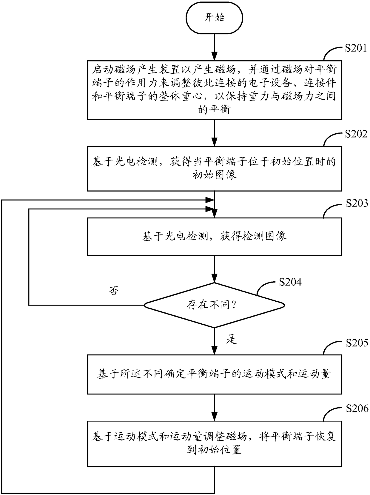
[0031] First, refer to figure 2 A shake correction method according to an embodiment of the present invention is described. The shake correction method can be applied to a shake correction devi...


PUM


Abstract

A jitter correction method and a jitter correction apparatus are disclosed. The jitter correction method comprises: after the electronic device is connected to the jitter correction device, starting the magnetic field generating means to generate a magnetic field, and adjusting the integral center of gravity of the electronic device, the connecting member and the balance terminal connected to eachother by the force of the magnetic field on the balance terminal to maintain a balance between gravity and magnetic field force; obtaining an initial image when the balance terminal is at an initialposition and a detection image thereafter based on photoelectric detection; determining a motion mode and a motion amount of the balance terminal based on the difference when the initial image is different from the detection image; and adjusting a magnetic field based on the motion mode and the motion amount to restore the balance terminal to an initial position.

Description

technical field [0001] The present invention relates to anti-shake technology, more specifically, to a shake correction method and shake correction equipment based on photoelectric detection and magnetic levitation. Background technique [0002] Most of the current anti-shake technologies are used in camera equipment. Camera anti-shake technology mainly includes the following types: [0003] 1. Optical image stabilization (OIS), the basic principle is that the gyroscope in the lens detects a small movement, and the signal is sent to the microprocessor to immediately calculate the amount of displacement that needs to be compensated, and then through the compensation lens group, according to The shake direction and displacement of the lens are compensated, so as to effectively overcome the image blur caused by the vibration of the camera. [0004] 2. Sensor anti-shake (CCD / CMOS), the basic principle is to place the CCD on a bracket that can move up and down, left and right, ...

Claims


Application Information

Patent Timeline
IPC IPC(8): H04N5/232
CPCH04N23/682H04N23/6811H04N23/685
Inventor 廖可宫卫涛王炜于海华
Owner RICOH KK
Why Eureka
Try Eureka