Head and neck fixing device for promoting rehabilitation of hemiplegic patient

A technology of fixation device and head and neck is applied in the field of head and neck fixation device for promoting the rehabilitation of hemiplegic patients.

Active Publication Date: 2018-12-21
THE FIRST PEOPLES HOSPITAL OF NANTONG
View PDF11 Cites 10 Cited by
  • Summary
  • Abstract
  • Description
  • Claims
  • Application Information

AI Technical Summary

Problems solved by technology

At the same time, the affected limbs of the hemiplegic patients lose the relaxation support of the muscles. Once the lying position is not good, complica

Method used


Image

  • Head and neck fixing device for promoting rehabilitation of hemiplegic patient
  • Head and neck fixing device for promoting rehabilitation of hemiplegic patient
  • Head and neck fixing device for promoting rehabilitation of hemiplegic patient

Examples


Embodiment 1

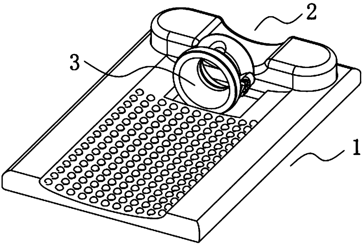
[0052] The following is attached Figure 1-9 The present invention is described in further detail.

[0053] A hemiplegic head and neck immobilization device, such as Figure 1-9 As shown, it includes a bottom support part 1, a head support part 2 and a neck fixing part 3. The head support part 2 is arranged on the upper side of the bottom support part 1, and the neck fixing part 3 is detachable. It is arranged on the upper part of the bottom support part 1, and the neck fixing part 3 is arranged adjacent to the head support part 2;

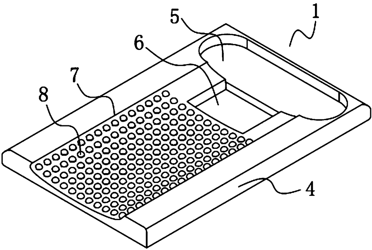
[0054] The bottom support part 1 includes a base plate 4, the upper part of the base plate 4 is provided with a placement groove 5 near one end edge thereof for placing the head support part 2, and the base plate 4 is adjacent to the placement groove 5 A through groove 6 for accommodating the neck fixing part 3 is opened at the position of the base plate 4, and an arc groove 7 is opened on the upper part of the bottom plate 4 aligned with its ot...

Embodiment 2

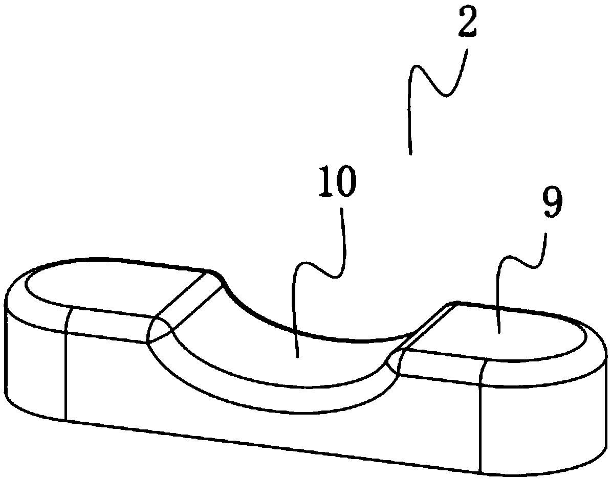
[0074] The difference from Example 1 is that the curved silica gel plate 10 is prepared by the following method:

[0075] Take the following raw materials and weigh them by weight: 35 parts of methyl vinyl phenyl silicone rubber, 18 parts of polyurethane, 8 parts of calcium carbonate powder, 9 parts of tourmaline powder, 4 parts of p-phenylenediamine, diethyl 3 parts of thiourea, 3 parts of paraffin oil and 2 parts of tricresyl phosphate;

[0076] S1. Add the weighed methyl vinyl phenyl silicone rubber and polyurethane into a pulverizer and pulverize until the particle diameter is 8mm, and the speed of the pulverizer is set to 700r / min to obtain a pulverized mixed material;

[0077] S2. Put the pulverized mixed material prepared in step S1 into a banbury mixer for banburying. The temperature of the banbury mixer is set at 190° C., the speed is set at 850 r / min, and the banburying time is 25 minutes to obtain banbury materials;

[0078] S3, adding the banburying material and ...

Embodiment 3

[0082] The difference from Example 1 is that the curved silica gel plate 10 is prepared by the following method:

[0083] Take the following raw materials and weigh them by weight: 40 parts of methyl vinyl phenyl silicone rubber, 20 parts of polyurethane, 10 parts of calcium carbonate powder, 10 parts of tourmaline powder, 5 parts of p-phenylenediamine, diethyl 4 parts of thiourea, 5 parts of paraffin oil and 3 parts of tricresyl phosphate;

[0084] S1. Add the weighed methyl vinyl phenyl silicone rubber and polyurethane into a pulverizer and pulverize until the particle diameter is 10mm, and the speed of the pulverizer is set to 800r / min to obtain a pulverized mixed material;

[0085] S2. Put the pulverized mixed material prepared in step S1 into a banbury mixer for banburying. The temperature of the banbury mixer is set at 200° C., the speed is set at 900 r / min, and the banburying time is 30 minutes to obtain banbury materials;

[0086] S3, adding the banburying material a...


PUM


Abstract

The invention discloses a head and neck fixing device for promoting rehabilitation of a hemiplegic patient. The head and neck fixing device comprises a bottom supporting part, a head supporting part and a neck fixing part. The head supporting part is arranged on one side of the upper portion of the bottom supporting part, the neck fixing part is detachably arranged on the upper portion of the bottom supporting part, and the neck fixing part and the head supporting part are adjacently arranged. The bottom supporting part comprises a bottom plate, a containing groove for containing the head supporting part is formed in the position, close to the edge of one end, of the upper portion of the bottom plate, a through groove for containing the neck fixing part is formed in the position, adjacentto the containing groove, of the bottom plate, and an arc-shaped groove is formed in the position, aligned to the edge of the other end, of the upper portion of the bottom plate. The head and neck fixing device provides a good posture rehabilitation environment for the hemiplegic patient, certain complications are avoided, posture rehabilitation of the hemiplegic patient is promoted, and the headand neck fixing device is worthy of popularization.

Description

technical field [0001] The invention relates to the technical field of medical instruments, more specifically, it relates to a head and neck immobilization device for promoting recovery of hemiplegic patients. Background technique [0002] Hemiplegia is also called hemiplegia, which refers to the dyskinesia of the upper and lower extremities, the facial muscles and the lower part of the tongue muscle on the same side, and is a common symptom of acute cerebrovascular disease. Although patients with mild hemiplegia can move, when they walk, their upper limbs tend to bend, their lower limbs straighten, and the paralyzed lower limbs take a step and draw half a circle. This special walking posture is called hemiplegic gait. Severe cases are often bedridden and lose their ability to live. According to the degree of hemiplegia, it can be divided into paresis, incomplete paralysis and total paralysis. Paresis: manifested by weakened muscle strength, muscle strength is 4 to 5, gene...

Claims


Application Information

Patent Timeline
IPC IPC(8): A61F5/01A61F5/055A61G7/07A61H7/00C08L83/07C08L75/04C08L91/06C08K13/02C08K3/26C08K3/38C08K5/18C08K5/523B29C43/02
CPCA61F5/0102A61F5/055A61G7/07A61G2200/20A61H7/001A61H2201/1207A61H2201/1607A61H2201/1611A61H2205/02B29C43/003B29C43/02C08K2003/265C08K2003/387C08L83/04C08L2201/08C08L2205/03C08L75/04C08L91/06C08K13/02C08K3/26C08K3/38C08K5/18C08K5/523
Inventor 周三连陈黎敏黄志东
Owner THE FIRST PEOPLES HOSPITAL OF NANTONG
Why Eureka
Try Eureka