Bending following material support device

A follow-up and material-supporting technology, which is applied in the direction of feeding device, positioning device, storage device, etc., can solve the problems of no control system, unsatisfactory use, and unguaranteed safety and stability, so as to reduce the cost of upgrading, Good prospects for use and high flexibility

Pending Publication Date: 2018-12-21
深圳懒人自动化机械有限公司
View PDF0 Cites 9 Cited by
  • Summary
  • Abstract
  • Description
  • Claims
  • Application Information

AI Technical Summary

Problems solved by technology

[0002] The supporting device of the bending machine is used for bending the workpiece by the bending machine, and the follow-up supporting car that follows the workpiece to lift the function, reduces labor intensity, improves efficiency, and reduces labor costs. It is widely used in the sheet metal industry. The existing The bending follow-up supporting device cannot meet the needs of people;
[0003] The existing bending follow-up supporting device has certain disadvantages in use. Firstly, the bending machine cannot be quickly replaced for use. It can only be matched with the manufacturer's own bending machine system and specific models. It has very high requirements for the CNC system of the bending machine. In addition, it does not have an independent control system and cannot exchange signals with the bending machine. Safety and stability cannot be guaranteed. , Finally, the position information of the slider of the bending machine cannot be obtained, the synchronous action with the bending machine cannot be guaranteed, and the CNC bending machine and ordinary bending machine cannot be used universally, which has brought a certain impact on people's use process. For this reason, we Propose a bending follow-up support device

Method used


Image

  • Bending following material support device
  • Bending following material support device
  • Bending following material support device

Examples


Embodiment 1

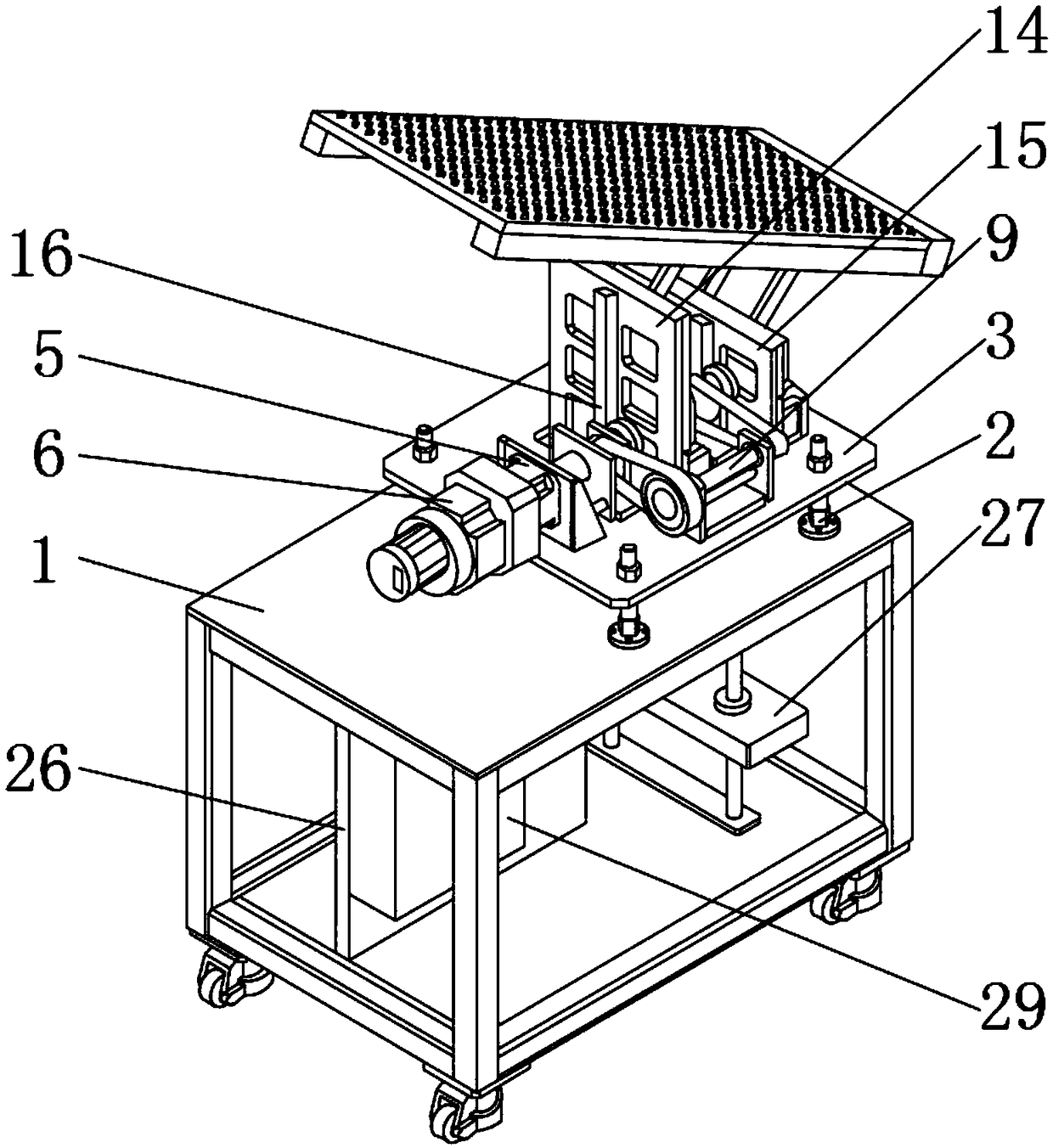
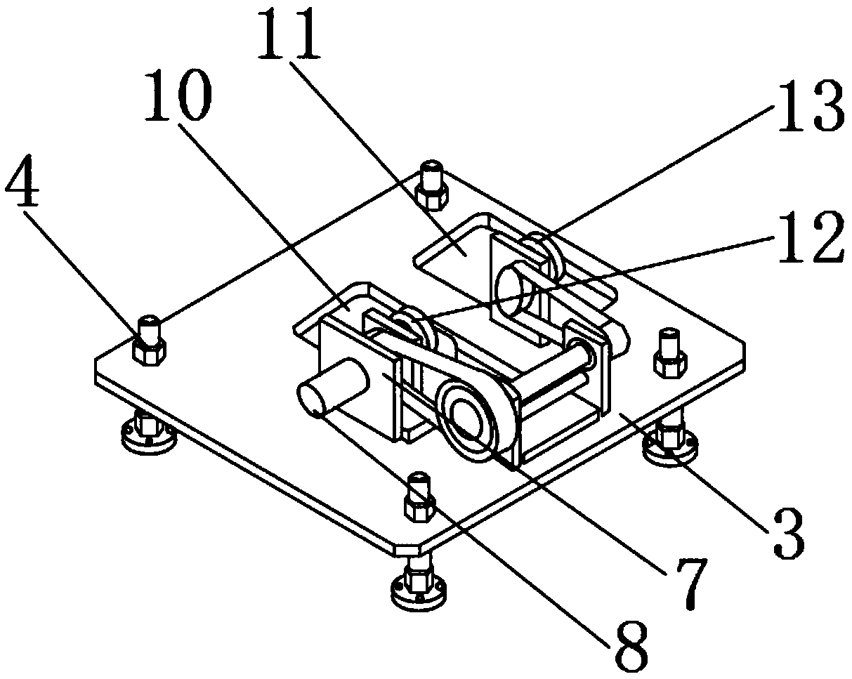
[0028] Such as Figure 1-5 As shown, a bending follow-up supporting device includes a frame 1, four sets of screws 2 are fixedly installed on the outer surface of the upper end of the frame 1, and the upper ends of the four sets of screws 2 are provided with a main mounting plate 3. The upper end of the plate 3 is fixedly installed with four sets of nuts 4, and the four sets of screws 2 correspond to the four sets of nuts 4 one-to-one. The upper side of the main mounting plate 3 is fixedly installed with a motor mount 5, and the upper end of the motor mount 5 is fixedly installed There is a motor 6, the rear end of the motor mounting seat 5 is fixedly installed with a support frame 7, one side of the motor 6 is provided with a rotating shaft 8, and the rotating shaft 8 penetrates the inner center of the support frame 7, and one side of the support frame 7 is provided with a synchronization With a deceleration structure 9, the main mounting plate 3 is provided with a main liftin...

Embodiment 2

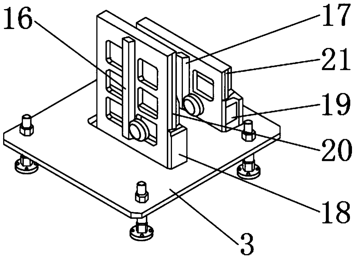
[0030] Such as Figure 1-5 As shown, the No. 1 guide rail 20 is movably connected with the No. 1 slide block 18, the No. 2 guide rail 21 is movably connected with the No. 2 slide block 19, and the No. 1 guide rail 20 is movably connected with the No. 1 slide block 18, and the No. 2 guide rail 21 and the No. 2 slide block are movably connected. 19 all constitute a sliding rail pair, the first gear 12 is movably connected with the first rack 16, the second gear 13 is movably connected with the second rack 17, and the first gear 12 is movably connected with the first rack 16 and the second gear 13 The second rack 17 constitutes a rack and pinion pair. The synchronous belt reduction structure 9 is composed of a bracket, a transmission shaft, a main transmission belt and a secondary transmission belt. The first gear 12 is movably connected with the transmission shaft through the main transmission belt, and the second gear 13 is connected to the transmission shaft. The main lifting s...


PUM


Abstract

The invention discloses a bending following material support device. The bending following material support device comprises a rack. Four screws are fixedly arranged on the outer surface of the upperend of the rack. The upper ends of the four screws are provided with a main installing plate in a penetration manner. Four nuts are fixedly arranged at the upper end of the main installing plate. Thefour screws correspond to the four nuts in a one-to-one manner. A motor installing base is fixedly arranged on one side of the upper end of the main installing plate. The bending following material support device is provided with an aviation connector, the screws and a programmable servo control unit, a bending machine can be rapidly replaced for usage, die height replacement for the bending machine can be achieved, an independent control system is arranged and can exchange communication signals with the bending machine, and safety and stability can be guaranteed. The bending machine sliding block position information is obtained, synchronous actions with the bending machine are guaranteed, and precision is very high; and the bending following material support device can be commonly used for a numerical control bending machine and an ordinary bending machine, certain practicability is achieved, and better usage prospects are brought.

Description

Technical field [0001] The invention relates to the technical field of sheet metal cold bending forming, in particular to a bending follow-up material supporting device. Background technique [0002] When the supporting device of the bending machine is used for the bending of the workpiece, the follow-up carrier with the lifting function of the workpiece can be used to reduce labor intensity, improve efficiency, and reduce labor costs. It is widely used in the sheet metal industry. The bending follow-up supporting device cannot satisfy people's use; [0003] The existing bending follow-up supporting device has certain disadvantages when in use. Firstly, the bending machine cannot be quickly replaced and used. Secondly, it cannot meet the height of the mold change of the bending machine. The existing bending follow-up supporting device It can only be matched with the manufacturer's own bending machine system and specific models. It has very high requirements on the CNC system of th...

Claims


Application Information

Patent Timeline
Patent Type & Authority Applications(China)
IPC IPC(8): B21D43/20
CPCB21D43/20
Inventor 赵宏伟
Owner 深圳懒人自动化机械有限公司
Why Eureka
Try Eureka