
Pouring die storing device for steel manufacturing

A technology for pouring molds and steel, applied in the field of steel manufacturing, can solve the problems of molten steel splashing out, molten steel falling down, hurting workers, etc., and achieve the effects of preventing dumping, increasing blocking area, and blocking sputtering

Active Publication Date: 2018-12-21
金华市亚轮机械有限公司
View PDF12 Cites 1 Cited by
  • Summary
  • Abstract
  • Description
  • Claims
  • Application Information

AI Technical Summary

Problems solved by technology

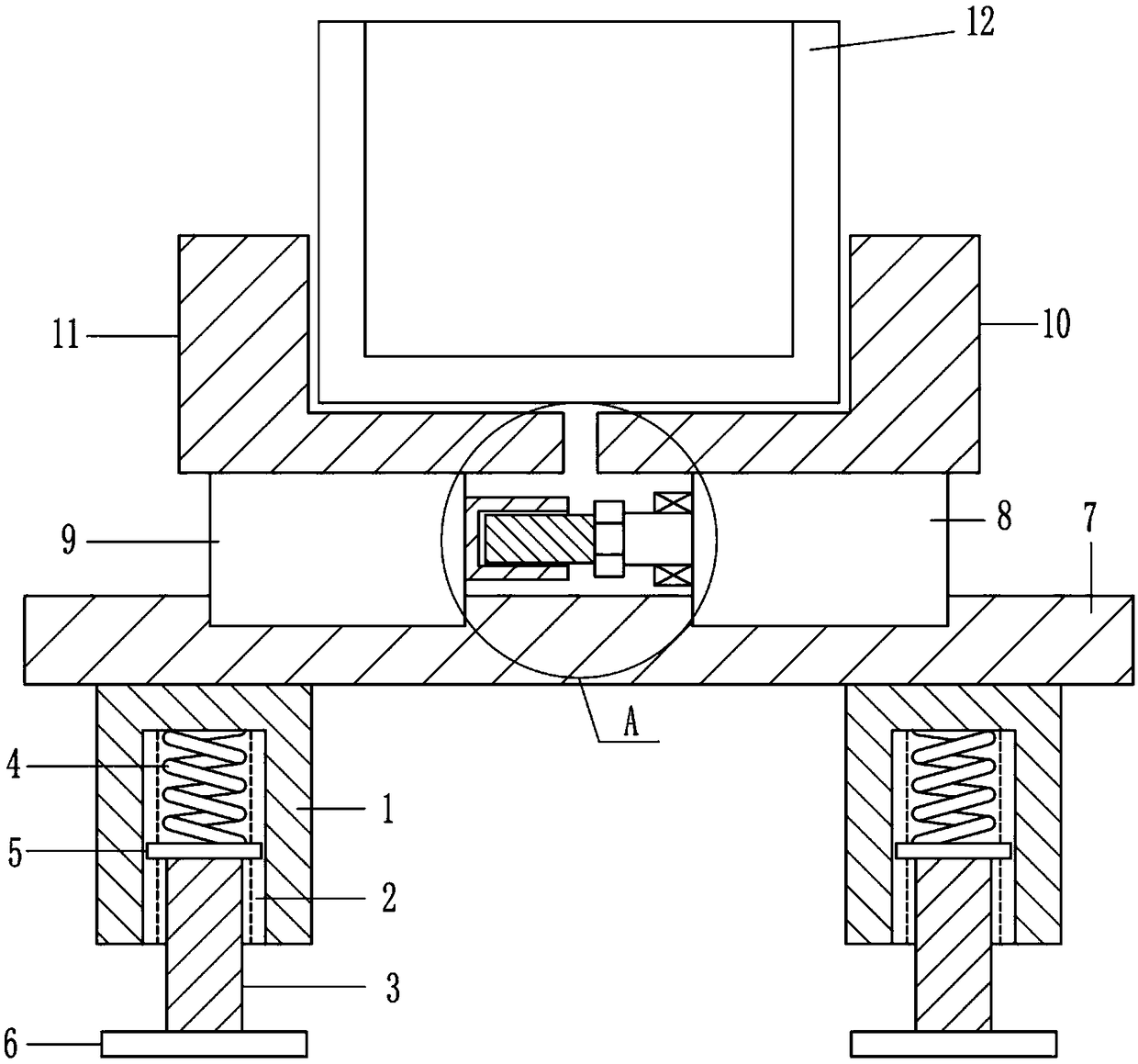
[0002] Put the pig iron for steelmaking into the steelmaking furnace and smelt it according to a certain process to obtain steel. In order to obtain different shapes of steel, it is necessary to pour the molten steel into ingot molds of different shapes. During the pouring process, the melting The temperature of the molten steel itself is relatively high. When it is poured from the furnace into the ingot mold, the molten steel will produce an impact force during the contact with the mold, which will cause the molten steel to splash out. The high-temperature molten steel will hurt the workers around it, and the mold will If there is no device for fixed placement for support, it is also easy to pour down the molten steel. Therefore, it is urgent to develop a casting mold placement device for steel manufacturing that can fix the casting mold to improve pouring safety.

Method used


Image

  • Pouring die storing device for steel manufacturing
  • Pouring die storing device for steel manufacturing
  • Pouring die storing device for steel manufacturing

Examples


Embodiment

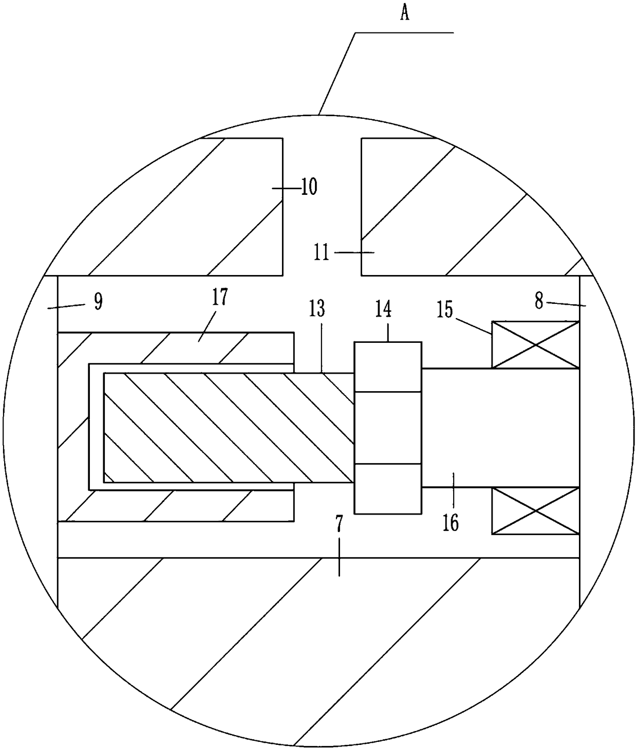
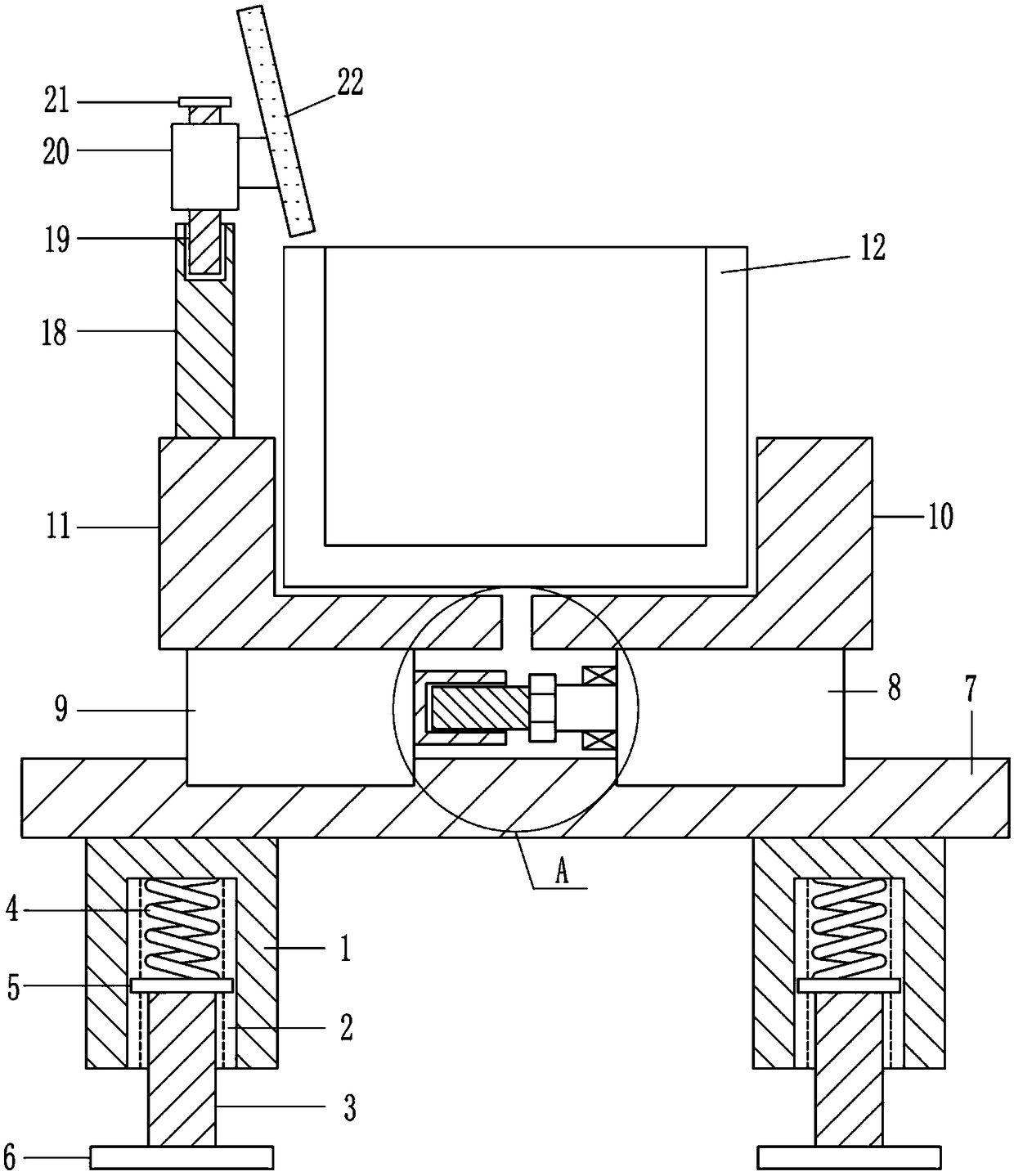
[0023] A pouring mold placement device for iron and steel fabrication, such as Figure 1-7 As shown, it includes a support tank 1, a telescopic rod 3, an elastic member 4, a first slider 5, a support plate 6, a slide rail 7, a second slider 8, a third slider 9, and a first L-shaped shelf 10. The second L-shaped placing frame 11, pouring container 12, screw rod 13, roller 14, bearing seat 15, rotating shaft 16 and threaded groove body 17; two supporting groove bodies 1 are fixedly connected to the bottom surface of slide rail 7 in turn, and the supporting groove body 1 is provided with a chute 2; the telescopic rod 3 is inserted into the support tank 1, and is slidably connected to the chute 2 through the first slider 5; the first slider 5 is connected to the inner top of the support tank 1 through the elastic member 4; The support plate 6 is fixed on the bottom of the telescopic rod 3; the first L-shaped shelf 10 is slidably connected to the slide rail 7 through the second sli...


PUM


Abstract

The invention relates to the field of steel manufacturing, in particular to a pouring die storing device for steel manufacturing. The technical effects that the pouring die storing device for steel manufacturing can fix a pouring die and improve the safety of pouring are achieved. The pouring die storing device for steel manufacturing comprises supporting groove bodies, telescopic rods, elastic pieces, first sliding blocks, supporting plates, a sliding rail, second sliding blocks, a third sliding block, a first L-shaped storing frame, a second L-shaped storing frame, a pouring container, a screw rod, a roller, a bearing seat, a rotating shaft and a threaded groove body; and the two supporting groove bodies are sequentially and fixedly connected with the bottom face of the sliding rail, a sliding groove is formed in each supporting groove body, the telescopic rods extend into the supporting groove bodies and are slidably connected with the sliding grooves through the first sliding blocks, and the first sliding blocks are connected with the inner tops of the supporting groove bodies through the elastic pieces. The pouring die storing device for steel manufacturing achieves the effects of fixing the pouring die and improving the pouring safety.

Description

technical field [0001] The invention relates to the field of iron and steel manufacturing, in particular to a pouring mold placement device for iron and steel manufacturing. Background technique [0002] Put the pig iron for steelmaking into the steelmaking furnace and smelt it according to a certain process to obtain steel. In order to obtain different shapes of steel, it is necessary to pour the molten steel into ingot molds of different shapes. During the pouring process, the melting The temperature of the molten steel itself is relatively high. When it is poured from the furnace into the ingot mold, the molten steel will produce an impact force during the contact with the mold, which will cause the molten steel to splash out. The high-temperature molten steel will hurt the workers around it, and the mold will If there is no device for fixed placement to support, it is also easy for molten steel to pour down, so there is an urgent need to develop a casting mold placement ...

Claims


Application Information

Patent Timeline
Patent Type & Authority Applications(China)
IPC IPC(8): B22D7/12
CPCB22D7/12
Inventor 程爱佳苗海春章福军
Owner 金华市亚轮机械有限公司
Learn More