Automatic pushing conveying device

A technology of a conveying device and a pushing device, which is applied in the field of mechanical processing, can solve the problems of laborious manual pushing, low processing efficiency and labor, and achieve the effect of accurate cutting and positioning.

Inactive Publication Date: 2018-12-21
江门市森联木业有限公司
View PDF5 Cites 1 Cited by
  • Summary
  • Abstract
  • Description
  • Claims
  • Application Information

AI Technical Summary

Problems solved by technology

[0002] In the processing of profiles by existing machine tools such as sawing machines, most of the smaller rod-shaped materials are bundled and stacked and then transported to the saw blade of the saw machine for fixed processing to improve processing efficiency. The abutment plate perpendicular to the feeding direction of the profile, the whole bundled profile is conveyed until the end faces are abutted against the abutment plate for positioning, not only determines the cutting length but also ensures that there is no deviation in the profile cutting, after that the fixing device starts to clamp, the saw blade The back and forth cutting is completed; however, whether the end face of the bundled profile in the existing processing is completely abutted against the abutment plate so that the saw blade does not deviate when cutting is determined by manually pushing the profile and judging that the end face of the profile is completely abutted according to the inability to move The positioning is completed accurately; this method is not only laborious but also time-consuming, and the overall processing efficiency is low; and when the processing profile is long, manual push is more laborious

Method used


Image

  • Automatic pushing conveying device

Examples


Embodiment Construction

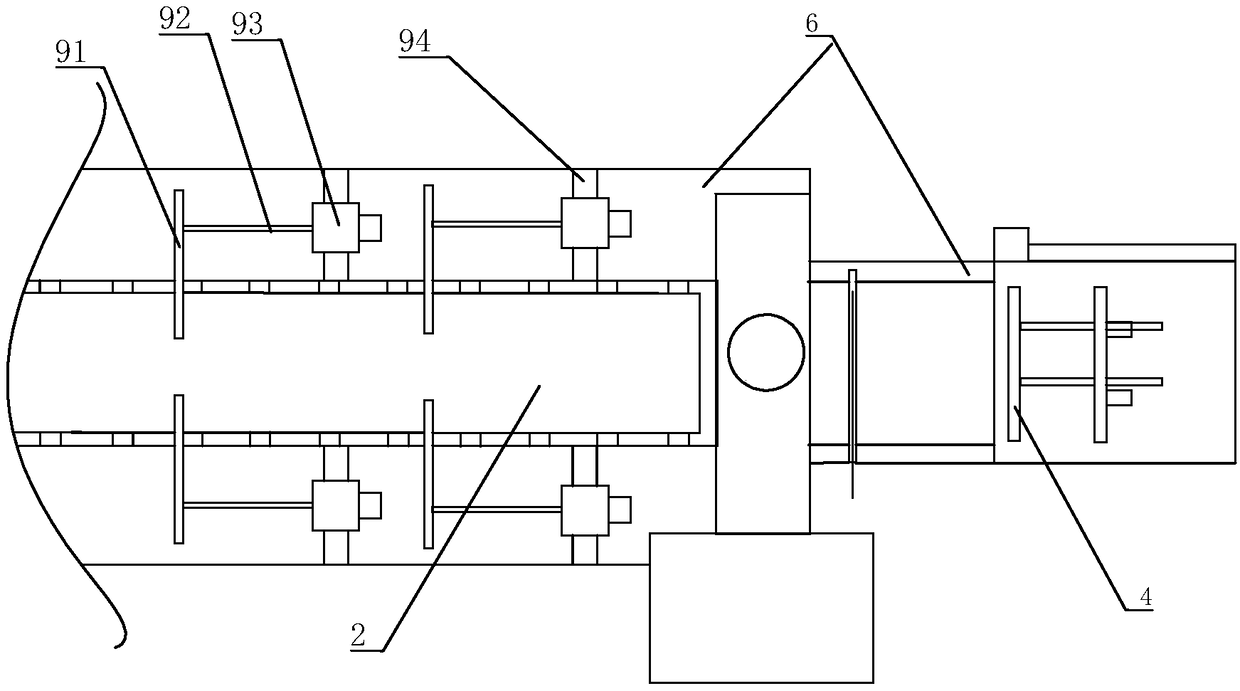
[0013] refer to figure 1 , a kind of automatic push conveying device of the present invention, comprises frame 6, is arranged on the conveyor belt 2 on described frame 6, and the front end of described conveyor belt 2 is provided with conveying roller, and described conveying roller is connected with driving motor to be driven by described The drive motor is driven to rotate, the front end of the frame 6 is provided with a positioning abutment plate 4, and the positioning abutment plate 4 is perpendicular to the length direction of the conveyor belt 2; the frame 6 is provided with a plurality of positioning pushers in sequence, The positioning push device includes a push plate 91 perpendicular to the length direction of the conveyor belt 2, a hydraulic device 92 that promotes the push plate 91 to move back and forth, and a mobile frame 93 for the hydraulic device 92 to be installed. 6 is provided with a sliding groove 94, the sliding groove 94 is perpendicular to the length di...


PUM


Abstract

The invention discloses an automatic pushing conveying device. The automatic pushing conveying device comprises a machine frame and a conveyor belt arranged on the machine frame; the front end of theconveyor belt is provided with a conveying roller; the conveying roller is connected with a driving motor so as to be driven by the driving motor to rotate; the front end of the machine frame is provided with a positioning abutting plate; the positioning abutting plate is perpendicular to the length direction of the conveyor belt; a plurality of positioning pushing devices are sequentially arranged on the machine frame from front to back; each positioning pushing device comprises a pushing plate, a hydraulic device for pushing the pushing plate to move back and forth, and a moving frame for mounting the hydraulic device; the moving frames are slidably connected with the machine frame; the pushing plates of the multiple positioning pushing devices are sequentially driven by the moving frames to move to the position above the conveyor belt, and then driven by the hydraulic devices to move forwards so as to push the side, not abutting against the positioning abutting plate, of profile tomove forward, due to the fact that the multiple positioning pushing devices are sequentially moved and matched, the automatic pushing conveying device can be used for automatic feeding of longer profile on the conveyor belt, and accurate cutting and positioning are ensured.

Description

technical field [0001] The invention relates to the field of mechanical processing, in particular to a feeding device of a mechanical processing machine tool. Background technique [0002] In the processing of profiles by existing machine tools such as sawing machines, most of the smaller rod-shaped materials are bundled and stacked and then transported to the saw blade of the saw machine for fixed processing to improve processing efficiency. The abutment plate perpendicular to the feeding direction of the profile, the whole bundled profile is conveyed until the end faces are abutted against the abutment plate for positioning, not only determines the cutting length but also ensures that there is no deviation in the profile cutting, after that the fixing device starts to clamp, the saw blade The back and forth cutting is completed; however, whether the end face of the bundled profile in the existing processing is completely abutted against the abutment plate so that the saw b...

Claims


Application Information

Patent Timeline
Patent Type & Authority Applications(China)
IPC IPC(8): B23Q7/00
CPCB23Q7/003
Inventor 谭炳灿
Owner 江门市森联木业有限公司
Why Eureka
Try Eureka