Eureka AIR delivers breakthrough ideas for toughest innovation challenges, trusted by R&D personnel around the world.

Box girder rubber tube drawing assisting device and manufacturing method thereof

A manufacturing method and rubber tube technology, which are applied to ceramic forming cores, ceramic forming mandrels, etc., can solve the problems of low protection, complicated operation, low work efficiency, etc., and achieve saving work time, simple and fast operation, and high work efficiency. Effect

Pending Publication Date: 2018-12-21
CR10BG NO 3 CONSTR
View PDF0 Cites 0 Cited by
  • Summary
  • Abstract
  • Description
  • Claims
  • Application Information

AI Technical Summary

Problems solved by technology

[0004] Aiming at the deficiencies of the prior art, the present invention provides a box girder rubber tube extraction device and its manufacturing method, which solves the problem that the rubber tube is usually used to form a hole in the prestressed channel of the railway prefabricated box girder. After the hole is formed, the rubber tube usually uses a sling Wrapped around the pipe head and pulled out by the hoist, this way of pulling out the pipe will first damage the rubber pipe, causing the rubber pipe to break and remain in the concrete. The later opening of the pipe will have a negative impact on the overall force of the box girder, and the operation is complicated , the practicability is not strong; and its speed is difficult to control when the tube is pulled out, and the rubber tube is prone to high-speed rebound when it exits the hole, causing safety hazards to personnel and equipment. It is more dangerous and less protective, and its practicability is not strong ; and most of the equipment will need to constantly change the position of the extubation sling due to the length of the rubber tube and the limitation of the site, and this will increase the working time, the work efficiency is low, and the practicability is not strong.

Method used


Image

  • Box girder rubber tube drawing assisting device and manufacturing method thereof
  • Box girder rubber tube drawing assisting device and manufacturing method thereof

Examples


Embodiment Construction

[0023] The following will clearly and completely describe the technical solutions in the embodiments of the present invention with reference to the accompanying drawings in the embodiments of the present invention. Obviously, the described embodiments are only some, not all, embodiments of the present invention. Based on the embodiments of the present invention, all other embodiments obtained by persons of ordinary skill in the art without making creative efforts belong to the protection scope of the present invention.

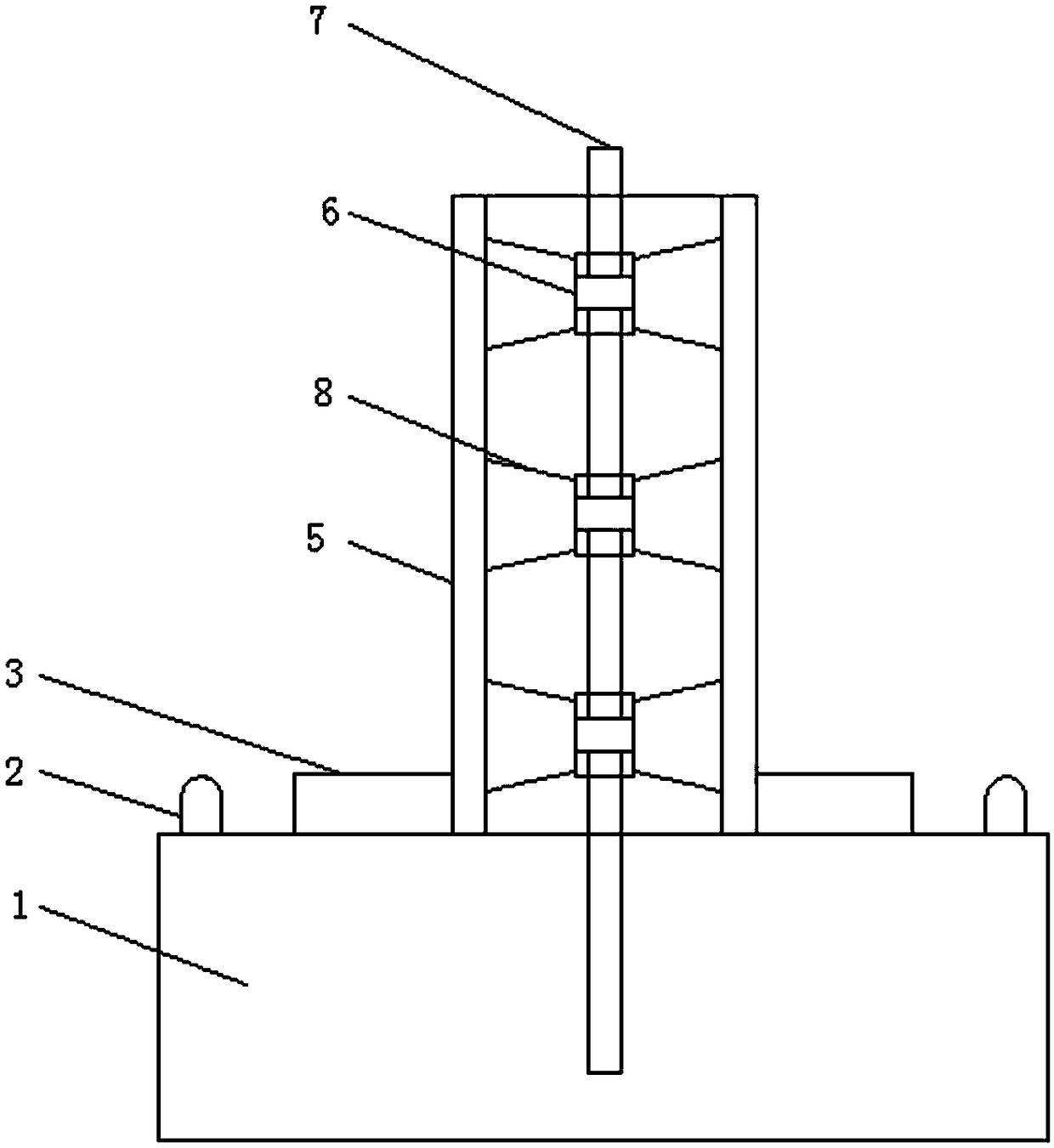
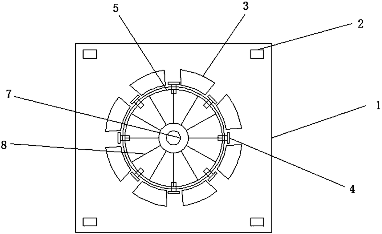
[0024] The embodiment of the present invention provides a box girder rubber tube extraction device and a manufacturing method thereof, such as Figure 1-2 As shown, including the base 1, the axle 4 is installed in the base 1, and the upper outer wall of the base 1 is installed with the lifting lug 2 and the anti-tilt platform 3, and the steel column 7 is installed at the center of the outer wall above the base 1, and the steel column 7 is covered with A rotati...


PUM

PropertyMeasurementUnit
Diameteraaaaaaaaaa

Abstract

The invention discloses a box girder rubber tube drawing assisting device and a manufacturing method thereof. The box girder rubber tube drawing assisting device comprises a base; wheel shafts are installed in the base, and lifting lugs and anti-tilt tables are installed on the outer wall above the base; and the center of the outer wall above the base is provided with a steel column, the steel column is sleeved with rotating bearings, the rotating bearings are sleeved with supporting ribs, and the supporting ribs are sleeved with a roller. According to the box girder rubber tube drawing assisting device, the roller is arranged, a traditional winch type drawing rubber tube process is improved, the self-made drawing assisting device is added between a winch and a rubber tube, so that the action direction of the force is changed, the rubber tube can be completely drawn out once, and the rubber tube is prevented from being damaged, the rubber tube is prevented from being broken and left ina concrete, so that the situation that adverse effects on the overall stress of a box girder when a hole is opened to take out the rubber tube at the later stage can be avoided, the operation is simple and fast, and the practicability is high.

Description

technical field [0001] The invention relates to the technical field of civil engineering, in particular to a box girder rubber pipe extraction device and a manufacturing method thereof. Background technique [0002] At present, the prestressed channel of the railway prefabricated box girder adopts the method of pumping rubber into the hole. After the hole is formed, the rubber tube is usually wrapped around the tube head with a sling and pulled out by the hoist. This method of pulling out the tube will first damage the rubber tube, causing the rubber tube to break and remain in the concrete. The later opening of the tube to take the tube will have a negative impact on the overall force of the box girder. The operation is complicated and the practicability is not strong; The speed of the tube is difficult to control, and the rubber tube is prone to high-speed rebound when it exits the hole, causing safety hazards to personnel and equipment. And space limitation, need constan...

Claims


Application Information

Patent Timeline
IPC IPC(8): B28B7/28
CPCB28B7/285
Inventor 马晓冬褚付启王勇渠立明
Owner CR10BG NO 3 CONSTR
Why Eureka
Eureka Blog
Learn More