A split shaft tube

A split-type, shaft-tube technology, applied in axles, wheels, transportation and packaging, etc., can solve the problems of space occupation, poor cooling effect, shaft tube damage, etc., to prolong service life, easy to disassemble and install , time-saving effect

Inactive Publication Date: 2018-12-21
十堰合强工贸有限公司
View PDF0 Cites 0 Cited by
  • Summary
  • Abstract
  • Description
  • Claims
  • Application Information

AI Technical Summary

Problems solved by technology

[0004] The purpose of the present invention is to provide a split shaft tube to solve the problem that the split shaft tube proposed in the above background technology rarely has a right coolant cavity, and the shaft tube is prone to damage due to partial overheating during the working process, perhaps Some heat dissipation and cooling devices are installed, because they cannot contact with the shaft tube, it is like scratching the boots to achieve a good cooling effect, and it also takes up space.

Method used


Image

  • A split shaft tube
  • A split shaft tube
  • A split shaft tube

Examples


Embodiment Construction

[0019] The following will clearly and completely describe the technical solutions in the embodiments of the present invention with reference to the accompanying drawings in the embodiments of the present invention. Obviously, the described embodiments are only some, not all, embodiments of the present invention. Based on the embodiments of the present invention, all other embodiments obtained by persons of ordinary skill in the art without making creative efforts belong to the protection scope of the present invention.

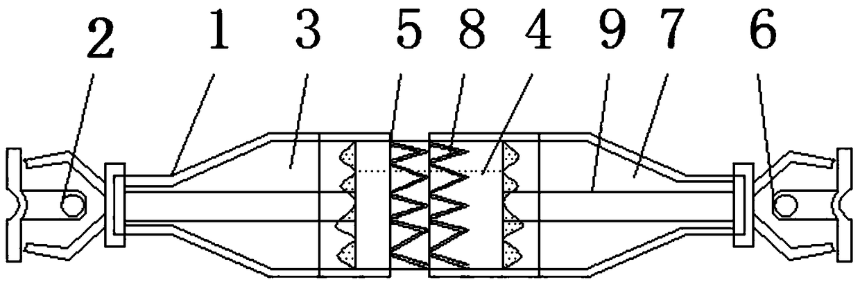
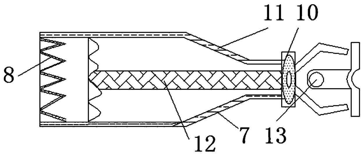
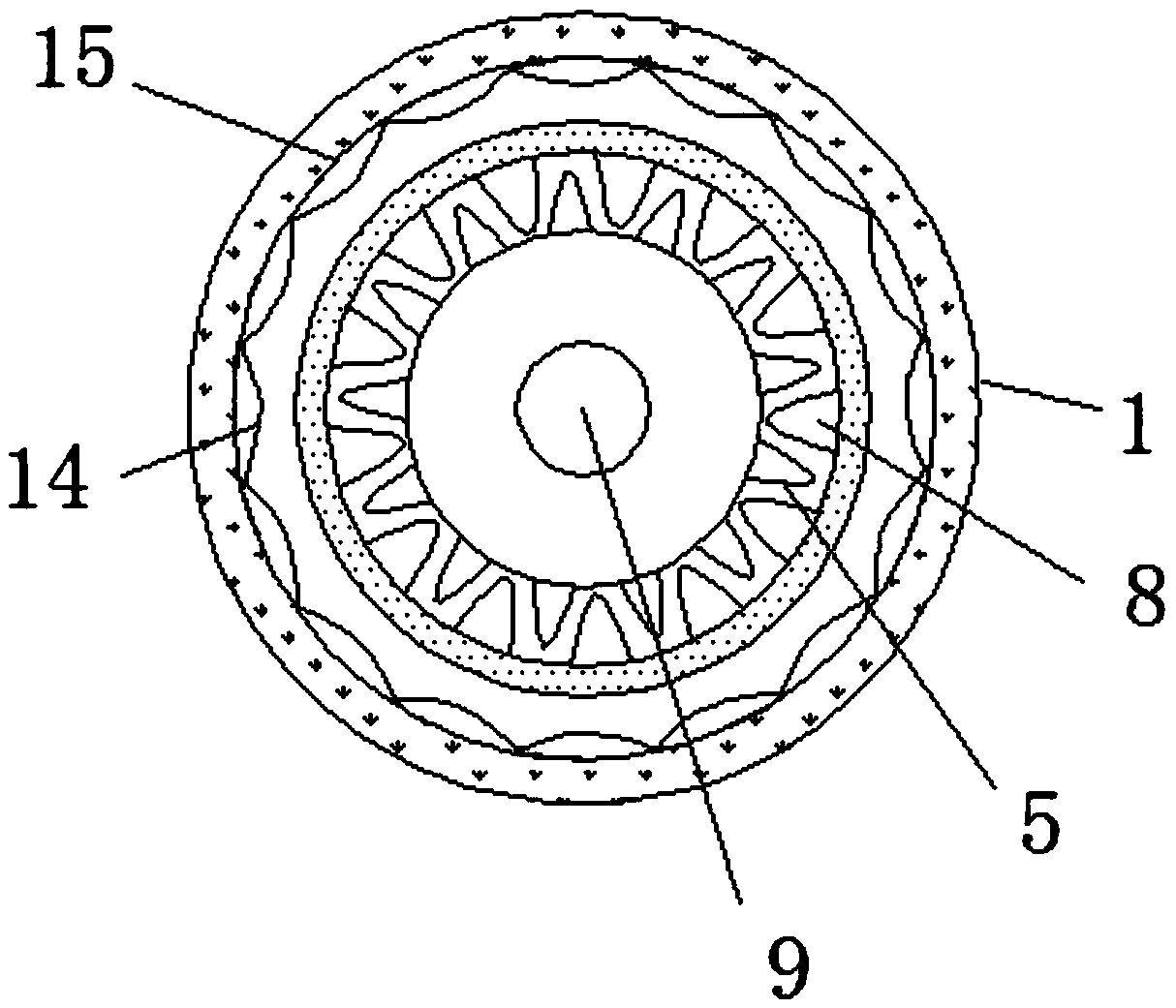
[0020] see Figure 1-3 , the present invention provides a technical solution: a split shaft tube, including shaft tube main body 1, left shaft fork 2, left reducer tube 3, spline sleeve 4, thread protrusion 5, right shaft fork 6, right Reducer tube 7, thread groove 8, main shaft tube 9, sealing groove ring 10, reinforcing rib 11, shaft sleeve 12, dosing port 13, limit ferrule 14 and coolant chamber 15, the leftmost end of shaft tube main body 1 The left shaft...


PUM


Abstract

A split shaft tube includes a shaft tube body and a threaded groove, the leftmost end of the shaft tube main body is provided with a left shaft fork, and the right end of the left shaft fork is fixedly connected with a left diameter changing pipe, the right end of the left variable diameter pipe is connected with a spline sleeve through clamping and nesting, and the rightmost end of the left variable diameter pipe is provided with a threaded protrusion by welding, The rightmost end of the shaft tube main body is provided with a right shaft fork, and the left end of the right shaft fork is provided with a right variable diameter pipe; the threaded groove is installed on the leftmost end of the right variable diameter pipe by welding; the innermost ring of the threaded groove is provided with a main shaft tube; the outer wall of the main shaft tube is nested and installed with a shaft sleeve; and an agent feeding port is arranged in the inner middle of the right shaft fork. The split axle tube is symmetrical with respect to the vertical centerline of the axle tube main body through the left axle fork and the right axle fork, so that the axle tube main body is more simple and labor-free when working, and the axle tube main body is designed as a symmetrical structure, and the axle tube main body can be uniformly forced, and the service life of the axle tube main body can be prolonged.

Description

technical field [0001] The invention relates to the technical field of split shaft tubes, in particular to a split shaft tube. Background technique [0002] The split shaft tube is a tube formed by turning the ends of the partitions in the same direction and connecting them to each other. It is an important part of the drive axle assembly. It is integrated with the drive axle housing to fix the axial relative positions of the left and right drive wheels. It supports the mass of the frame and the assemblies on it, and at the same time bears the road surface reaction force and moment transmitted from the wheels when the car is running, and transmits it to the frame through the suspension. And high-quality carbon structural steel and alloy structural steel hot-rolled seamless steel pipes for axle tubes of drive axle housings. [0003] Split shaft tubes on the market rarely have a right coolant chamber, and the shaft tube is prone to damage due to local overheating during work....

Claims


Application Information

Patent Timeline
IPC IPC(8): B60B35/14B60B35/16
CPCB60B35/14B60B35/16
Inventor 崔胜黄振杨运杰杨涛
Owner 十堰合强工贸有限公司
Why Eureka
Try Eureka