A conveying device for truss loading

The technology of a conveying device and a truss is applied in the field of conveying devices for truss loading to achieve the effects of improving loading efficiency, simple and compact structure, and fast reversing speed.

Active Publication Date: 2021-04-23
芜湖固高自动化技术有限公司
View PDF6 Cites 0 Cited by
  • Summary
  • Abstract
  • Description
  • Claims
  • Application Information

AI Technical Summary

Problems solved by technology

Therefore, it is necessary to use a conveying device to convey the material, but the existing conveying device still has many deficiencies and needs to be improved urgently

Method used


Image

  • A conveying device for truss loading

Examples


Embodiment Construction

[0018] Below, the technical solution of the present invention will be described in detail through specific examples.

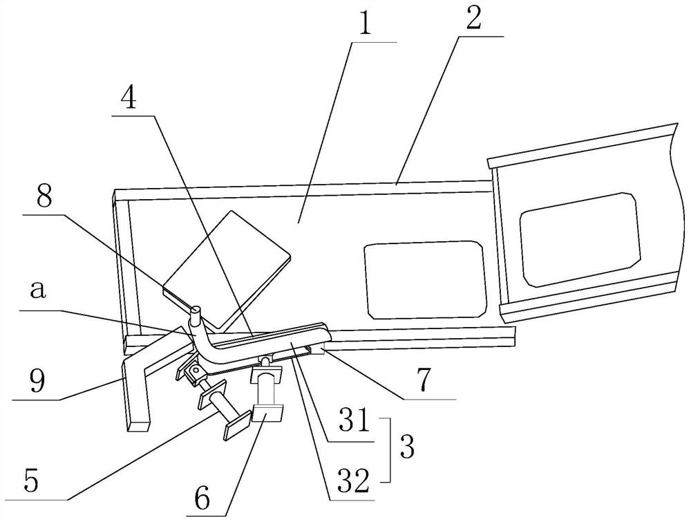
[0019] Such as figure 1 as shown, figure 1 It is a structural schematic diagram of a conveying device for truss loading proposed by the present invention.

[0020] refer to figure 1 , a conveying device for truss loading proposed by an embodiment of the present invention, comprising: a conveyor belt 1, guard plates 2 located on both sides of the conveyor belt 1, and a driving mechanism for driving the conveyor belt 1 to carry out the conveying action, wherein: one side of the conveyor belt 1 A reversing baffle plate 3, a push plate 4, a first power mechanism 5 and a second power mechanism 6 are provided.

[0021] The place face of reversing baffle 3 is positioned at the top of conveyor belt 1 conveying surface, and reversing baffle 3 comprises upper baffle 31 and lower baffle 32, and upper baffle 31 and lower baffle 32 are arranged up and down and pre-set b...


PUM


Abstract

The invention discloses a conveying device for truss loading, comprising: a conveying belt, guard plates located on both sides of the conveying belt, and a driving mechanism for driving the conveying belt to carry out conveying action; plate, a first power mechanism and a second power mechanism; the reversing baffle includes an upper baffle and a lower baffle arranged up and down, and one end of the upper baffle and the lower baffle rotates through the adapter seat and the guard plate on one side of the conveyor belt The upper baffle and the lower baffle are both provided with a bending part on the side away from the adapter seat; the push plate is located between the upper baffle and the lower baffle, and one end of the push plate is rotatably connected with the adapter seat; the first The power mechanism is used to drive the end of the reversing baffle away from the adapter to swing left and right along the conveying direction of the belt feeding direction, and the second power mechanism is used to drive the end of the push plate away from the adapter to swing left and right along the conveying direction of the conveyor belt. The invention can reverse the direction of the bagged material on the conveyor belt, and does not need to stop the conveying work during the reversing process.

Description

technical field [0001] The invention relates to the technical field of automatic transportation, in particular to a conveying device for truss loading. Background technique [0002] With the development of the economy, the production level continues to increase. After the production of bagged finished materials such as cement and flour is completed, the materials need to be placed on the transport vehicle. Therefore, a conveying device is needed to convey materials, but the existing conveying devices still have many deficiencies and need to be improved urgently. Contents of the invention [0003] Based on the technical problems existing in the above-mentioned background technology, the present invention proposes a conveying device for truss loading. [0004] The present invention proposes a conveying device for truss loading, including: a conveyor belt, guard plates located on both sides of the conveyor belt, and a driving mechanism for driving the conveyor belt to carry ...

Claims


Application Information

Patent Timeline
Patent Type & Authority Patents(China)
IPC IPC(8): B65G47/52B65G47/24B65G47/82
CPCB65G47/24B65G47/52B65G47/82
Inventor 于晓东冯沉冲左勤平
Owner 芜湖固高自动化技术有限公司
Why Eureka
Try Eureka