
A kind of flow booster reversing valve

A technology of flow boosting and reversing valves, which is applied in the field of hydraulic devices, can solve the problems of insufficient liquid flow response and insufficient reversing effects, and achieve the requirements of reversing, simple structure, and large reversing force. Effect

Active Publication Date: 2021-06-11
湖北创偲诺电气科技股份有限公司
View PDF8 Cites 0 Cited by
  • Summary
  • Abstract
  • Description
  • Claims
  • Application Information

AI Technical Summary

Problems solved by technology

[0003] In industrial equipment, the reversing valve with relatively large flow of fluid usually uses a solenoid valve. The control accuracy and flexibility of the solenoid valve are relatively ideal, but the reversing force generated by it is fixed, which affects the flow rate of the liquid. The response effect is not good enough, especially in the condition of large flow or abnormal increase of flow, the commutation effect is not good enough

Method used


Image

  • A kind of flow booster reversing valve
  • A kind of flow booster reversing valve
  • A kind of flow booster reversing valve

Examples


Embodiment Construction

[0024] Bonded below Figure 1-5 And the embodiments are further described in detail in the present invention:

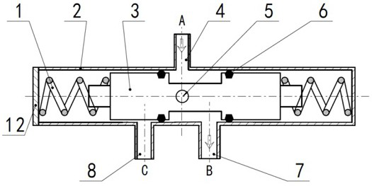
[0025] A flow boost-type commutation valve comprising a valve body 2, a valve stem 3, a hydraulic pilot lever 5, and a rotating electric machine 11; two sides of the valve body 2 having a rectangular curved valve body for cancel the current reset The reset spring 1; the side surface of the valve body 2 is also mounted for the valve body cover 12 of the valve body 2, and the valve body cover 12 and the valve body 2 are attached to the valve body 2; the valve body 2 is also attached to the motor cover 9 for closure valve body. The liquid in the 2nd there is an outlet of the power supply line in the motor cover 9, and the motor cover 9 also protects the rotary electric machine 10; the rotary electric machine 11 is connected by the power supply line, because the motor cover 9 during operation The fluid is filled with liquid, so the rotary electric machine 10 employs a motor t...


PUM


Abstract

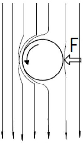
The invention discloses a flow-assisted reversing valve, which belongs to the technical field of hydraulic devices and includes a valve body, a valve stem, a hydraulic lever and a rotating motor. Return springs installed on both sides of the valve body are used to cancel the current of the valve body The valve stem is used to switch the flow direction of the liquid. It has a cylindrical boss with a dumbbell-shaped structure. The two sides are used to install the return spring. The middle is the guide part. The middle position has a transparent hollow for placing the hydraulic lever. The liquid seal between the rod and the valve body is realized by the sealing ring, and the rotating motor above the valve body drives the hydraulic lever, and the force generated by the Magnus effect is used to realize the reversing under the condition of fluid flow. The reversing force generated by the invention increases with the increase of the liquid flow velocity, has self-adaptive characteristics, and can realize greater reversing force than conventional electromagnetic valves under the condition of relatively large flow velocity.

Description

Technical field [0001] The present invention relates to the technical field of hydraulic devices, in particular, a flow boost-type commutation valve belongs to a reversing valve having an adaptive force, which provides a larger commutation force for a high flow rate. Background technique [0002] The reversing valve is a directional control valve having two or more fumes and two or more oil ports, and is a valve that realizes the communication, cutting and commutation of the hydraulic oil flow, and the valve of the pressure unloading and sequential operation. It can be divided into manual commutation. Valves, electromagnetic replacement valves, electric-liquid replacement valves, etc. The reversing valve has a wide range of applications in industries such as oil and chemical. [0003] The commutation valves in the industrial equipment for the commutation of the commutation are generally adopted by the soleness and flexibility of the electromagnetic valve, the control accuracy and...

Claims


Application Information

Patent Timeline
Patent Type & Authority Patents(China)
IPC IPC(8): F15B13/02
CPCF15B13/021
Inventor 王春生李宽吴士宾
Owner 湖北创偲诺电气科技股份有限公司
Learn More