
Hoisting device for port wharf construction

A hoisting device and wharf technology, which is applied to trolley cranes, hoisting equipment braking devices, cranes, etc., can solve the problems of gantry crane shaking or tipping, gantry crane damage, and lifting cargo damage, etc., to achieve safe use and improve operation. range, the effect of improving usability

Inactive Publication Date: 2018-12-21
CHINA MARITIME POLICE ACADEMY
View PDF12 Cites 3 Cited by
  • Summary
  • Abstract
  • Description
  • Claims
  • Application Information

AI Technical Summary

Problems solved by technology

[0005] Aiming at the deficiencies of the prior art, the present invention provides a lifting device for port and wharf construction. The crane is not restricted by the rails through the wheels and can move freely, which greatly improves the operating range and flexibility of the crane. Fix the crane firmly to the ground to prevent the crane from toppling or shaking during hoisting or typhoon weather, and then increase the ability of the crane to conduct maritime monitoring through the watchtower, improve the practicability of the crane and other advantages, and solve the problem that the gantry crane can only be fixed according to The trajectory movement of the gantry crane is limited, and it is affected by the typhoon. At the same time, when the gantry crane is hoisting goods, the rollers on the lower surface of its feet are fixed on the track and fixed to the left, so that the gantry crane will shake or fall, which is easy to cause damage to the hoisted goods. Or the damage of the gantry crane, the gantry crane is only used as a hoisting workpiece in the port, and the problem of reduced practicability

Method used

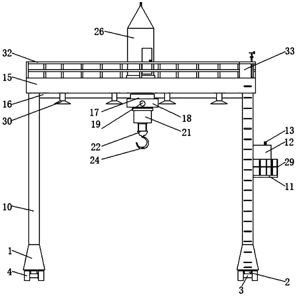
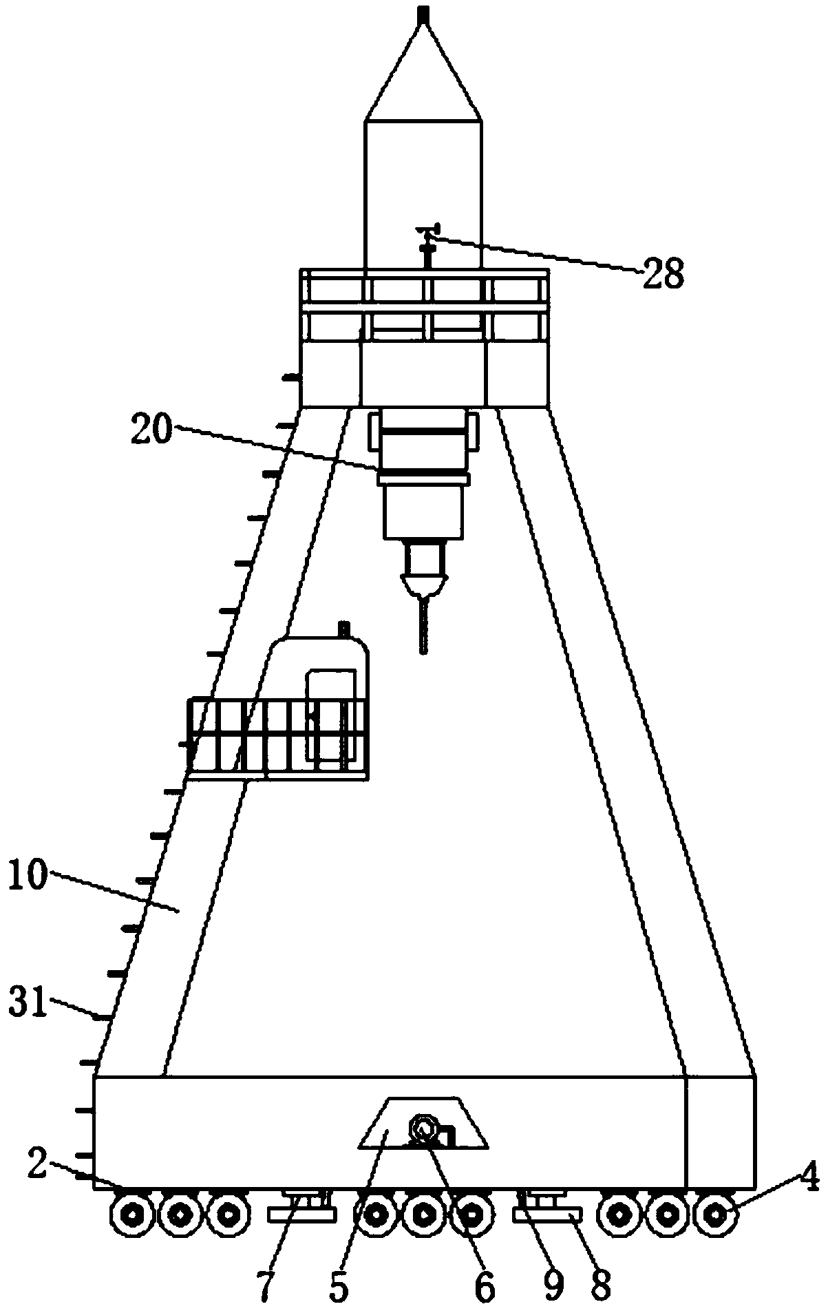

Image

  • Hoisting device for port wharf construction
  • Hoisting device for port wharf construction
  • Hoisting device for port wharf construction

Examples


Embodiment Construction

[0032] The following will clearly and completely describe the technical solutions in the embodiments of the present invention with reference to the accompanying drawings in the embodiments of the present invention. Obviously, the described embodiments are only some, not all, embodiments of the present invention. Based on the embodiments of the present invention, all other embodiments obtained by persons of ordinary skill in the art without making creative efforts belong to the protection scope of the present invention.

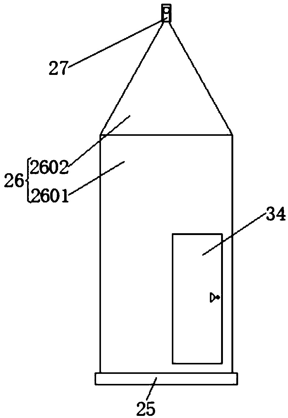
[0033] see Figure 1-7, a kind of hoisting device for harbor wharf construction, comprises horizontal frame 1, and horizontal frame 1 is arranged symmetrically on left and right sides, and the lower surface of horizontal frame 1 is fixedly installed with rotating shaft 2 at intervals, and the lower surface of rotating shaft 2 is fixed wheel fork 3, The left and right sides of the wheel fork 3 are fixedly connected with the wheels 4, and the rotating shaft 2 ab...


PUM

PropertyMeasurementUnit
Widthaaaaaaaaaa

Abstract

The invention relates to the technical field of port wharf construction equipment, and discloses a hoisting device for port wharf construction. The hoisting device comprises horizontal frames which are symmetrically arranged on the left and right sides. Rotating shafts are fixedly mounted on the lower surface of each horizontal frame at intervals, wheel forks are fixed to the lower surfaces of therotating shafts, and wheels are fixedly connected with the left and right sides of each wheel fork. Mounting grooves are formed in the horizontal frames, vacuum pumps are fixedly mounted in the mounting grooves, two groups of hydraulic telescopic rods are fixedly mounted on the lower surface of each horizontal frame, and vacuum chucks are fixedly mounted on piston rods of the hydraulic telescopicrods. A crane is not restrained by a rail through the wheels, the crane can freely move, the operating range of the crane is greatly expanded, and flexibility of the crane is greatly improved; the crane is firmly fixed to the ground through the vacuum chucks, and the crane is prevented from toppling or shaking during hoisting or in typhoons; and the maritime affair monitoring capacity of the crane is added through a watchtower, so that practicability of the crane is improved.

Description

technical field [0001] The invention relates to the technical field of port and wharf construction equipment, in particular to a lifting device for port and wharf construction. Background technique [0002] Ports and wharfs are located along the coasts of seas, rivers, rivers, lakes, and reservoirs. They are transport hubs with waterway combined transport equipment and conditions for ships to safely enter, exit, and berth. , The place where ships berth, load and unload cargo, embark and disembark passengers, and replenish supplies. In the port terminal, in the process of collecting and distributing industrial and agricultural products and foreign trade import and export materials, it is necessary to use lifting devices to lift the materials collected or transported by water and land transportation to the transport vehicle or freighter, and complete the transshipment of the materials. [0003] At present, portal cranes, portal grab ship unloaders, bridge grab ship unloaders,...

Claims


Application Information

Patent Timeline
IPC IPC(8): B66C15/06B66C19/00B66C5/04
CPCB66C15/06B66C5/04B66C19/00
Inventor 张利娟
Owner CHINA MARITIME POLICE ACADEMY
Learn More