An oil injection device for an ultra-high pressure vessel

An oil injection device, ultra-high pressure technology, applied in distribution devices, special distribution devices, liquid distribution, transportation or transfer devices, etc., can solve the problems of container failure, damage, container material yield, etc., to improve reliability and simplify oil injection equipment , The effect of high oil injection pressure

Active Publication Date: 2019-11-15
NANJING UNIV OF SCI & TECH
View PDF5 Cites 0 Cited by
  • Summary
  • Abstract
  • Description
  • Claims
  • Application Information

AI Technical Summary

Problems solved by technology

When these two oil filling methods are in operation, the oil injection hole is in direct contact with the ultra-high pressure inside the container, so stress concentration easily occurs at the oil hole, which leads to material yield and damage of the container, which spreads to other parts of the container, resulting in Total failure of the container

Method used


Image

  • An oil injection device for an ultra-high pressure vessel
  • An oil injection device for an ultra-high pressure vessel
  • An oil injection device for an ultra-high pressure vessel

Examples


Embodiment approach

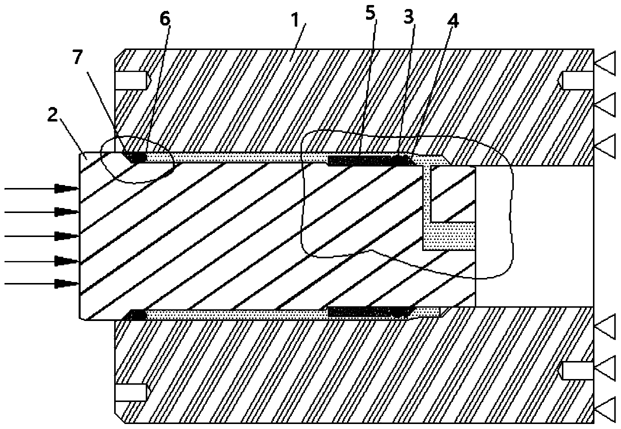
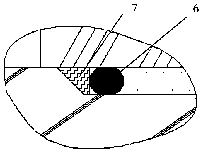
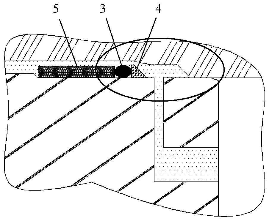
[0023] As an embodiment, the second sealing device includes a first sealing ring 3 and a second sealing ring 4; the first sealing ring is an elastic sealing ring, which acts as a low-pressure sealing; the second sealing ring is a metal sealing ring Ring, which acts as a high-pressure seal; the front end of the third round shaft 2-3 is covered with a first sealing ring 3 and a second sealing ring 4; the second sealing ring 4 is located at the front end of the first sealing ring 3; the third A positioning structure is provided on the round shaft 2-3 to axially position the first sealing ring 3; when pressure is applied to the rear end of the piston rod 2, the second sealing ring 4 is pushed to the second circular hole 1-2 and the third On the stepped surface of the round hole 1-3, the first sealing ring 3 is located in the second round hole 1-2, that is, when the pressure applied to the piston rod 2 is small, the first sealing ring 3 acts as a seal; when the pressure continues to...

Embodiment

[0035] The cylinder body 1 of the present invention does not have any oil injection holes, assuming that the inner diameter of the first round hole 1-1 of the cylinder body 1 is 81mm, and the outer diameter of the cylinder body 1 is 180mm; the diameter of the second round shaft 2-2 of the piston rod 2 is 68mm; Body 1 and piston rod 2 are both hot work die steel, yield strength σ s It is 1542MPa; Utilize ANSYS Workbench software to simulate and analyze the stress distribution state of cylinder body 1 in 500MPa hydrostatic sealing pressure environment, the result shows that the oil injection device of the present invention just does not have the small hole stress concentration problem, as Figure 9 shown; Figure 10 The stress distribution state of the cylinder with oil holes in the traditional technology cylinder, under the same sealing pressure and the same size conditions, the simulation results show that serious stress concentration occurs due to the connection between the o...


PUM


Abstract

The invention discloses an oil injection device of an ultrahigh pressure container. The oil injection device comprises an outer cylinder and a piston rod, the piston rod is arranged in the outer cylinder, a first round hole, a second round hole and a third round hole are formed in the outer cylinder, wherein the diameter of the first round hole, the diameter of the second round hole and the diameter of the third round hole are decreased in sequence, the piston rod comprises a first round shaft, a second round shaft and a third round shaft, wherein the diameter and the outer diameter of the first round shaft, the diameter and the outer diameter of the second round shaft and the diameter and the outer diameter of the third round shaft are decreased in sequence, the outer circle of the firstround shaft is matched with the first round hole, the outer circle of the third round shaft is matched with the third round hole, an oil storage cavity is formed between the outer circle of the secondround shaft and the second round hole, a first oil inlet hole is formed in the front end face of the third round shaft, a second oil inlet hole is formed in the radial direction of the third round shaft, the second oil inlet hole communicates with the first oil inlet hole, a first sealing device and a second sealing device sleeve the second round shaft and the third round shaft respectively, andthe two sealing devices are positioned through a step surface between the first round shaft and the second round shaft and a step surface between the second round shaft and the third round shaft correspondingly. The defect that stress concentration is generated at an oil hole due to the fact that an oil hole oil injection mode is adopted is overcome.

Description

technical field [0001] The invention belongs to the technical field of ultra-high pressure vessels, in particular to an oil filling device for ultra-high pressure vessels. Background technique [0002] The liquid pressure in the ultra-high pressure container is generally above 100 MPa, and some even reach several thousand MPa. The oil injection technology is the key technology to ensure the ultra-high pressure of the liquid in the container. At present, there are two main methods of oil injection into ultra-high pressure vessels: one is to directly open oil holes on the connecting parts of the vessel or the wall of the vessel, and then inject the oil through a hydraulic pump, for example, literature: Wu Bing. Magnesium Alloy Research on the design of pipe thermostatic liquid extrusion device (D). Nanjing: Nanjing University of Science and Technology, the oil filling method adopted for ultra-high pressure vessels, the medium liquid in the container is passed through a connect...

Claims


Application Information

Patent Timeline
Patent Type & Authority Patents(China)
IPC IPC(8): B67D7/02B67D7/06
CPCB67D7/0227B67D7/06
Inventor 赵孟军吴志林蔡红明
Owner NANJING UNIV OF SCI & TECH
Why Eureka
Try Eureka