
Warp sizing device
A technology of warp yarn sizing and size tank, which is applied in the field of cloth production and warp yarn production, and can solve problems such as uneven size, hard lumps, incomplete size extrusion, etc., and achieve uniform sizing effect
- Summary
- Abstract
- Description
- Claims
- Application Information
AI Technical Summary
Problems solved by technology
Method used
Image

Examples
Embodiment
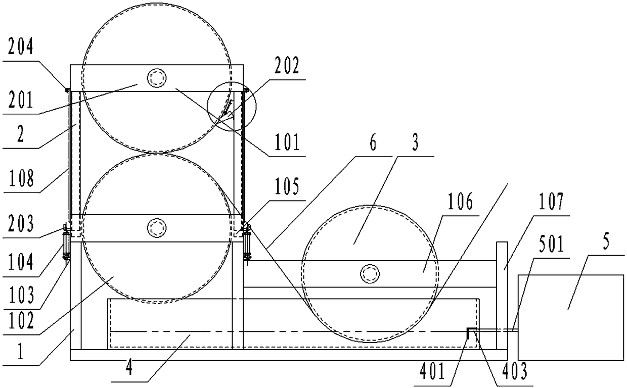
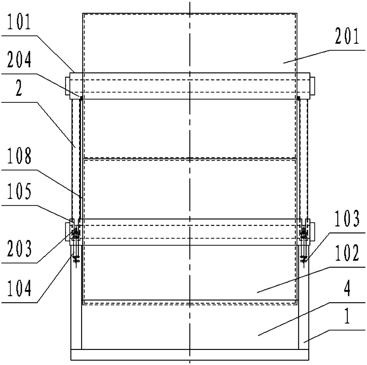
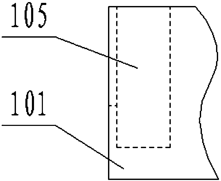
[0035] as attached figure 1 to attach Figure 10 Shown: a warp sizing device, including a lower bracket 1, a hoarding frame 101, a lower roller 102, a hanging ring 103, a spring 104, a rectangular slot 105, a right side plate 106, a right column 107, a slat 108, and an upper bracket 2. Upper roller 201, squeegee plate 202, hook 203, fixed block 204, dipping roller 3, pulp tank 4, position control groove 401, guide rib 402, lifting block 403, through hole 404, grouting cylinder 5, The size tube 501 and the warp yarn 6; the lower bracket 1 is a bracket structure welded by rectangular columns; the coaming frame 101 is a rectangular frame welded by four plates, and there are two places welded to the lower bracket 1 and the upper bracket 2; the lower roller 102 is connected to the lower panel frame 101 through a pin shaft, and can be used for radial rotation; the hanging ring 103 has four places, which are respectively welded to the front and rear of the left and right sides of th...
PUM
 Abstract
Description
Claims
Application Information