Automobile clutch

A technology of clutch and clutch cover, applied in the direction of clutch, friction clutch, mechanical drive clutch, etc., to achieve the effect of high transmission efficiency, safe and reliable operation, and improved joint smoothness

Inactive Publication Date: 2018-12-21
ANHUI UNIVERSITY OF TECHNOLOGY AND SCIENCE
View PDF6 Cites 1 Cited by
  • Summary
  • Abstract
  • Description
  • Claims
  • Application Information

AI Technical Summary

Problems solved by technology

[0005] Although the clutches in the above-mentioned comparative documents solve the corresponding practical problems, they do not solv

Method used


Image

  • Automobile clutch
  • Automobile clutch
  • Automobile clutch

Examples


Embodiment 1

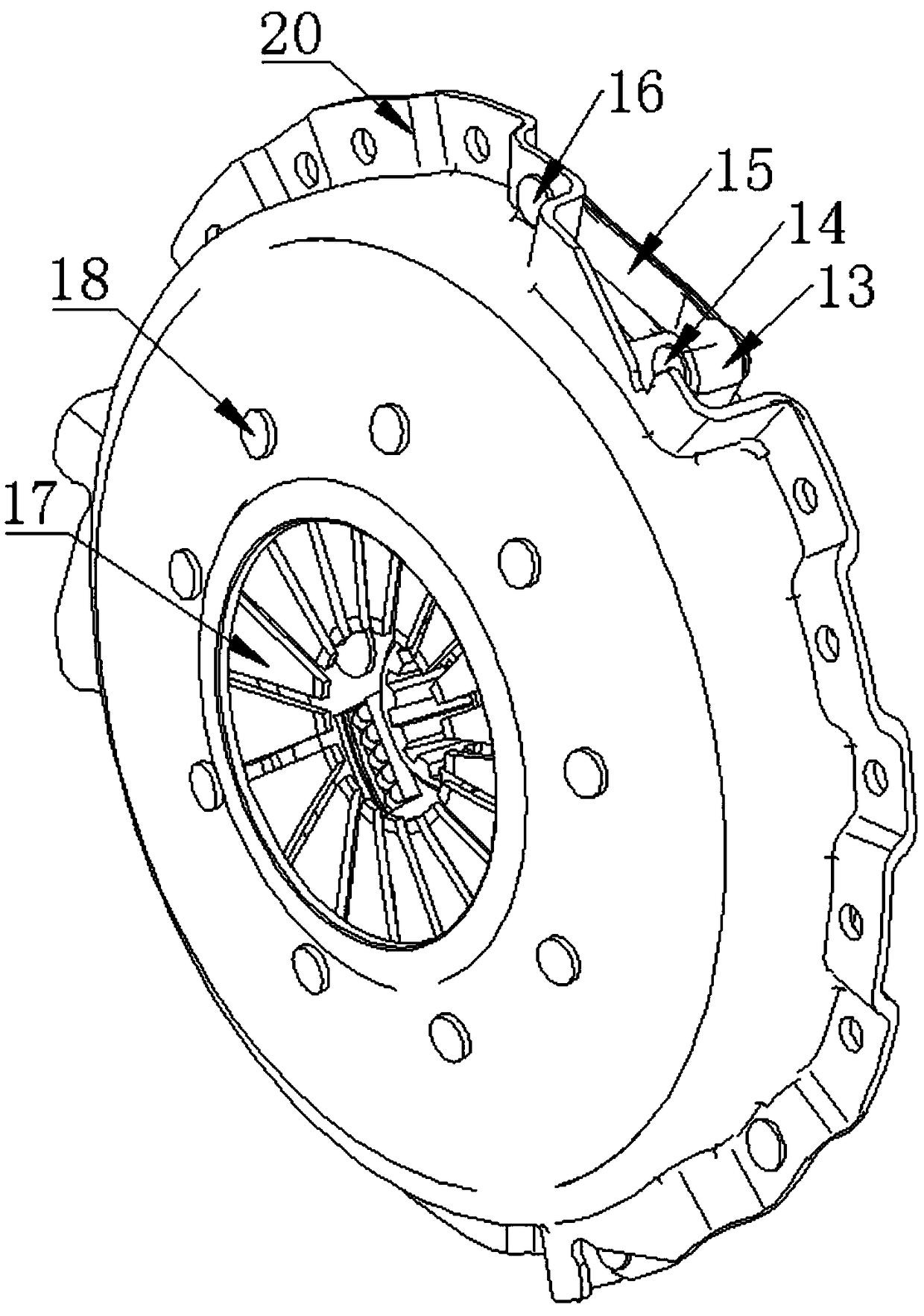
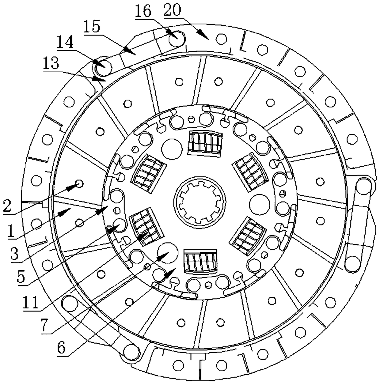
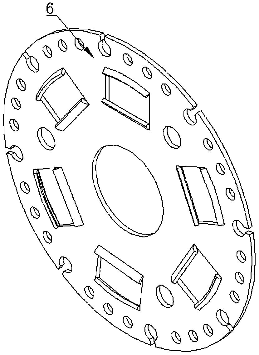
[0029] Such as Figure 1 to Figure 8 As shown, an automobile clutch includes a friction plate 1, a friction plate 2 4, and a connecting plate 3. The friction plate 1 and the friction plate 2 4 are symmetrically and coaxially distributed, and the connecting plate 3 is arranged on the friction plate. One 1 and the friction plate two 4 are connected by a rivet one 2, the connecting plate one 3 is connected with a transmission disk 6 through a rivet two 5, and the transmission disk 6 is connected with a damping disk 8 through a rivet three 7. The driven disk 6 and the damping disk 8 are arranged opposite to each other, and a driven disk hub 9 is provided therebetween. The center of the driven disk hub 9 is provided with a key groove, and the driven disk hub 9 is evenly distributed with rectangular shapes. The groove is provided with a spring 11 in the rectangular groove. A pressure plate 12 is arranged on the outer side of the friction plate 2 and the pressure plate 12 is evenly di...

Embodiment 2

[0034] Such as Figure 1 to Figure 8 As shown, an automobile clutch includes a friction plate 1, a friction plate 4, and a connecting plate 3. The friction plate 1 and the friction plate 2 4 are symmetrically and coaxially distributed, and the connecting plate 3 is arranged on the friction plate. One 1 and the friction plate two 4 are connected by a rivet one 2, the connecting plate one 3 is connected with a transmission disk 6 through a rivet two 5, and the transmission disk 6 is connected with a damping disk 8 through a rivet three 7. The driven disk 6 and the damping disk 8 are arranged opposite to each other, and a driven disk hub 9 is provided therebetween. The center of the driven disk hub 9 is provided with a key groove, and the driven disk hub 9 is evenly distributed with rectangular shapes. The groove is provided with a spring 11 in the rectangular groove. A pressure plate 12 is arranged on the outer side of the friction plate 2 and the pressure plate 12 is evenly dist...


PUM


Abstract

The invention discloses an automobile clutch, and relates to the technical field of automobile clutch design. The automobile clutch comprises a friction plate I, a friction plate II and a connecting piece I, wherein the connecting piece I is connected between the friction plate I and the friction plate II through a rivet I; the connecting piece I is connected to a driving disc through a rivet II;the driving disc is connected to a vibration reduction disc through a rivet III; a driven disc and the vibration reduction disc are oppositely arranged and a driven disc hub is arranged between the driven disc and the vibration reduction disc; a key groove is arranged in the center of the driven disc hub; rectangular grooves are uniformly arranged in the driven disc hub and a spring is arranged ineach rectangular groove; a pressure plate is arranged on the outer side of the friction sheet II; supports are uniformly arranged on the pressure plate; a connecting piece II is connected to each support through a rivet IV; a diaphragm spring is arranged on the outer side of the pressure plate; a clutch cover is arranged on the outer side of the diaphragm spring; the clutch cover is connected tothe diaphragm spring through a fixing pin; and the clutch cover is connected to the connecting piece II through a rivet V. The automobile clutch is simple and compact in structure, simple in force transmission mode, high in transmission efficiency and safe and reliable in working operation.

Description

Technical field [0001] The invention relates to the technical field of automobile clutch design, in particular to an automobile clutch. Background technique [0002] The clutch is an important part of the automobile transmission system, which realizes the disconnection or connection of the engine and the transmission. The output shaft of the clutch is the input shaft of the transmission, ensuring the smooth start of the automobile. When the car is running, the driver can step on or release the clutch pedal as needed to temporarily separate and gradually engage the engine and the gearbox to cut off or transmit the power input from the engine to the transmission. With the continuous improvement of the performance of automobile engines and the rapid development of automobile electronic technology, the performance of automobile clutches is also required to be improved. Therefore, improving the torque transmission capacity and enhancing the reliability of the clutch will become the m...

Claims


Application Information

Patent Timeline
IPC IPC(8): F16D13/38F16D13/58F16D13/71
CPCF16D13/385F16D13/585F16D13/71F16D2013/642
Inventor 陈玉程晶晶王鹏许高齐张新阳王思嘉何宏颖陈运洲
Owner ANHUI UNIVERSITY OF TECHNOLOGY AND SCIENCE
Why Eureka
Try Eureka