
Disk brake capable of monitoring force of disk spring in real time and monitoring method

A disc brake, real-time monitoring technology, applied in the field of sensors, can solve the problem of inability to accurately monitor the positive brake pressure and errors, and achieve the effects of wide practicability, improved reliability, and high measurement accuracy

Active Publication Date: 2018-12-21
CHINA UNIV OF MINING & TECH +2
View PDF7 Cites 7 Cited by
  • Summary
  • Abstract
  • Description
  • Claims
  • Application Information

AI Technical Summary

Problems solved by technology

In the current technology, the braking positive pressure is monitored to monitor the braking safety, but there is a large error between the positive pressure monitoring of the disc brake and the actual braking positive pressure of the disc brake, and it is impossible to accurately monitor the positive braking pressure.

Method used


Image

  • Disk brake capable of monitoring force of disk spring in real time and monitoring method
  • Disk brake capable of monitoring force of disk spring in real time and monitoring method
  • Disk brake capable of monitoring force of disk spring in real time and monitoring method

Examples


Embodiment Construction

[0014] The present invention will be further described below in conjunction with the embodiment in the accompanying drawings:

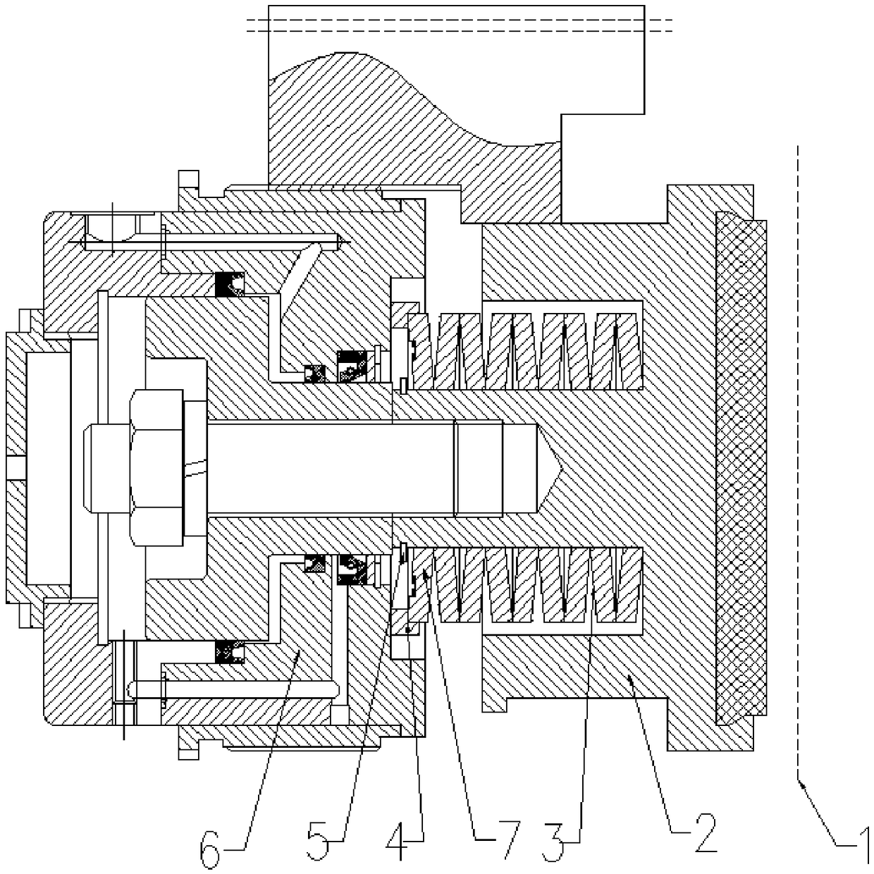
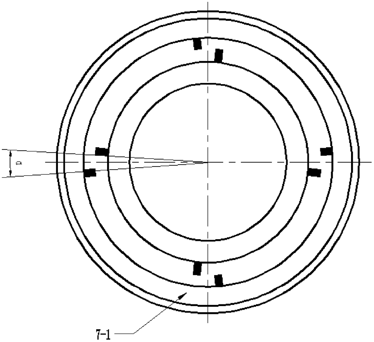
[0015] like figure 1 As shown, the disc brake of the present invention for monitoring disc spring force is mainly composed of a brake disc 1, a brake shoe assembly 2, a disc spring 3, a disc spring seat 4, a disc spring snap ring 5 and a hydraulic cylinder 6. A disc spring sensor 7 is provided between the disc spring seat 4 and the disc spring 3, and the external dimensions of the disc spring sensor 7 are the same as the disc spring 3, as figure 2 image 3 As shown, there are annular grooves on the opposite end faces on both sides of the disc spring sensor 7, and a plurality of strain gauges 7-1 arranged in pairs in the groove facing the end face of the disc spring seat 4, the paired arrangement The number of multiple strain gauges 7-1 is 6-10, which is determined according to the actual situation. figure 2 The a, b, and c shown in indicate the w...


PUM


Abstract

The invention provides a disk spring sensor capable of monitoring the force of a disk spring in real time and a method. A disk brake comprises a brake disk, a brake shoe assembly, the disk spring, a disk spring seat, a disk spring clamping ring and a hydraulic cylinder. The disk spring sensor is arranged between the disk spring seat and the disk spring, and the external dimension of the disk spring sensor is the same as that of the disk spring. The disk spring sensor has the double effects of disk spring stressing and sensor monitoring. Annular grooves are formed in the end faces of the disk spring sensor, and a plurality of strain gauges are arrayed in the grooves in pairs. The strain gauges which are arrayed in pairs are opposite and form a deflection angle alpha to be tightly attached to the inner diameter parts and the outer diameter parts of the annular grooves. A winding displacement hole in which a plurality of strain gauge wires are led out is formed in the radial direction ofthe disk spring sensor. By utilizing the limited space of an existing mine hoist disk brake structure, the disk spring sensor is installed to directly monitor the force of the disk spring without changing the original performance parameters of an existing brake and the structural dimensions of other parts, so that the fatigue of the disk spring is monitored, and the reliability of a hoist disk brake is greatly improved. The disk spring sensor is simple in structure, convenient to install and maintain and high in measuring precision.

Description

technical field [0001] The invention relates to a sensor, in particular to a disc spring sensor and a method for monitoring the force of a disc spring suitable for on-line monitoring of disc spring fatigue. Background technique [0002] The safe and reliable operation of the mine hoisting system will have positive significance for the country's economic development and people's living standards. The causes of coal mine safety accidents include many factors such as people, hoists, and the environment, among which insufficient positive pressure of disc brakes is a typical reason. In coal mine safety production, insufficient positive pressure of disc brakes is one of the main causes of lifting and transportation problems. [0003] The disc brake is an important braking unit on the hoist equipment, which is very important for the braking action of the hoist. Disc brakes are produced by butterfly springs and released by hydraulic pressure. When the hydraulic oil enters the hyd...

Claims


Application Information

Patent Timeline
IPC IPC(8): F16D66/00
CPCF16D66/00F16D2066/005F16D55/00
Inventor 徐桂云翟玉芳雷高阳张晓光刘珍孙佳胜张然孙正宋狄
Owner CHINA UNIV OF MINING & TECH
Learn More