Cyclone furnace denitration system and method

A cyclone furnace and denitration technology, which is applied in the combustion method, the combustion of lump fuel and powder fuel, and emission prevention, etc., can solve the problems of SCR catalyst poisoning, reduction of cyclone furnace emissions, and high cyclone furnace emissions, so as to ensure stable operation. , Ensure treatment efficiency and treatment effect, and reduce NOx emissions

Pending Publication Date: 2018-12-21
CHINA HUANENG GRP CO LTD +1
View PDF11 Cites 5 Cited by
  • Summary
  • Abstract
  • Description
  • Claims
  • Application Information

AI Technical Summary

Benefits of technology

This patented innovative nitridification technique involves combining two technologies - one called selective catalytic reducer (SCR) and another called ammoniating chemical reaction (SNCR). By utilizing this combination, it allows for effective control over emissions from various sources such as coal fired power plants without requiring expensive modifications like those previously mentioned. Additionally, by implementing these techniques separately within each specific location, there may also improve overall performance while minimizing costs associated with installation.

Problems solved by technology

This technical problem addressed by this patented describes how liquids from different sources contribute towards harmful emissions during the use of high-boiling (HB) coal in cyclones used for power generation. Cyclones require frequent cleanings because they tend to accumulate ash and slags onto their walls causing damage. Current methods like nitric acid injection cannot effectively remove these deposits without damaging the components inside the cycling machine itself.

Method used


Image

  • Cyclone furnace denitration system and method

Examples


Embodiment 1

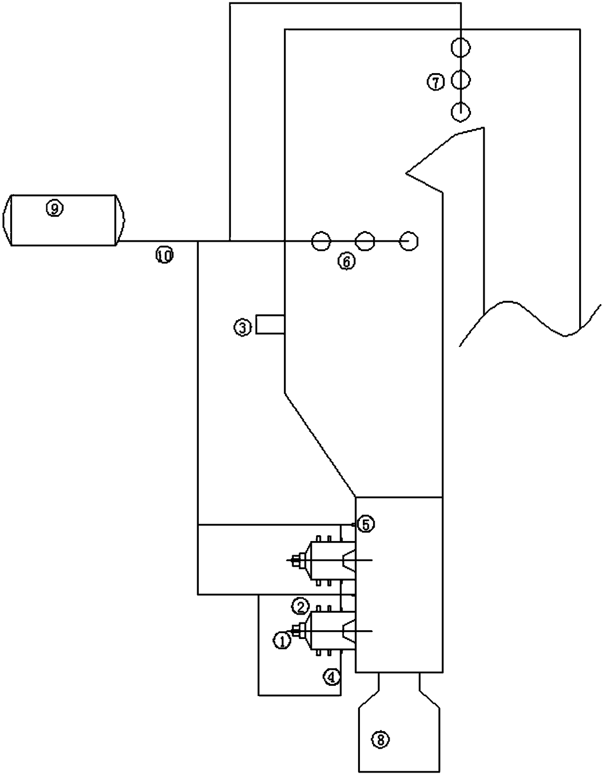
[0034] The present invention as figure 1 As shown, the cyclone furnace is equipped with two rows of cyclone burners; the primary air of the cyclone burner enters from the axial direction of the cyclone through the primary air inlet 1, and the secondary air of the cyclone burner enters from the cyclone through the secondary air inlet 2. The side wall of the cylinder enters tangentially, and part of the secondary air enters the furnace from the graded air inlet 3 on the upper part of the cyclone furnace furnace as graded wind; the first nozzle 4 of the amino reducing agent is arranged on the cylinder wall of the cyclone cylinder burner, and the amino reduction The second nozzle 5 of the agent is arranged on the side wall of the furnace above the cyclone burner; the first nozzle of the SNCR is arranged in the upper part of the furnace, and the second nozzle of the SNCR is arranged in the top flue of the furnace; the slag pool at the bottom of the cyclone furnace 8, and communicat...

Embodiment 2

[0038]Step 1: The coal powder is carried by the primary air, and enters the cyclone burner axially from the cyclone burner through the primary air inlet 1, and the secondary air enters the cyclone burner from the side wall of the cyclone burner through the secondary air inlet 2, At the same time, part of the secondary air enters the furnace interior through the grading air inlet 3 as the grading air;

[0039] Step 2: The pulverized coal entering the cyclone burner is ignited in the high-temperature reduction zone of the cyclone burner, and after burning, it forms liquid slag and flue gas carrying fly ash; the classified wind reduces the oxygen content in the combustion zone of the furnace, making the furnace The internal local area is in a reducing atmosphere as a whole, creating conditions for injecting the amino reducing agent; open the first nozzle 4 of the amino reducing agent or the second nozzle 5 of the amino reducing agent, and reduce the ammonia gas or urea and other a...


PUM


Abstract

The invention provides a cyclone furnace denitration system and method. The cyclone furnace denitration system comprises a cyclone cylinder combustor and a reducing agent storage tank which are connected with the cyclone furnace; an SNCR first nozzle is arranged at the upper part of a hearth of the cyclone furnace, and an SNCR second nozzle is arranged in the top of a hearth flue; the axial direction of the cyclone cylinder combustor is vertically mounted on the outer side wall of the lower part of the hearth of the cyclone furnace, the side wall of the cyclone cylinder combustor is provided with an amino reducing agent first nozzle, and an amino reducing agent second nozzle is arranged on the side wall of the hearth above the cyclone cylinder combustor; a primary air inlet is formed in the axial direction of the cyclone cylinder combustor, and a secondary air inlet is oppositely arranged in the tangential direction of the side wall; the reducing agent storage tank is correspondingly connected with the SNCR first nozzle, the SNCR second nozzle, the amino reducing agent first nozzle and the amino reducing agent second nozzle through a reducing agent conveying pipe. The cyclone furnace denitration system and method has the advantages that the process flow is simple, the storage and conveying equipment of the SNCR denitration reducing agent is fully utilized, a new reducing agentstorage and conveying device does not need to be added, so that a new combined denitration system is formed, and the low emission of NOx of the cyclone furnace is realized.

Description


Claims


Application Information

Patent Timeline
Owner CHINA HUANENG GRP CO LTD
Why Eureka
Try Eureka