Supercharge Your Innovation With Domain-Expert AI Agents!

Indoor unit of air conditioning system, control method and air conditioning system

A technology for air-conditioning systems and indoor units, applied in air-conditioning systems, noise suppression, refrigerators, etc., can solve problems affecting the control accuracy of electronic expansion valve 1, prone to gas-liquid two-phase state, large throttling noise, etc., to achieve Improve the effect of constant temperature dehumidification, improve user experience, and reduce working noise

Inactive Publication Date: 2018-12-21
GD MIDEA HEATING & VENTILATING EQUIP CO LTD +1
View PDF5 Cites 7 Cited by
  • Summary
  • Abstract
  • Description
  • Claims
  • Application Information

AI Technical Summary

Problems solved by technology

[0003] In the related technology, the constant temperature dehumidification technology mainly controls the start and stop of the compressor to ensure the room temperature, and some increase the outlet air temperature of the air conditioner by adding an electric auxiliary heating device, but this kind of heating and air supply will cause waste of energy. In order to reduce Energy consumption, the constant temperature dehumidification method that uses high temperature and high pressure refrigerant to heat and supply air came into being
[0004] like image 3 As shown, in the related art, in the constant temperature dehumidification method that uses high-temperature and high-pressure refrigerant to heat and supply air, when the indoor unit is performing constant temperature dehumidification, when the subcooling degree of the liquid pipe refrigerant coming out of the outdoor unit is insufficient, it is easy to produce gas-liquid In the two-phase state, it mixes with the refrigerant passing through the second valve (ie: electronic expansion valve 2) and then enters the first valve 1 (ie: electronic expansion valve 1), which will produce a lot of throttling noise, and the gas-liquid two-phase The state of the refrigerant will also affect the control accuracy of the electronic expansion valve 1

Method used


Image

  • Indoor unit of air conditioning system, control method and air conditioning system
  • Indoor unit of air conditioning system, control method and air conditioning system
  • Indoor unit of air conditioning system, control method and air conditioning system

Examples


Embodiment Construction

[0028] Embodiments of the present invention are described in detail below, examples of which are shown in the drawings, wherein the same or similar reference numerals designate the same or similar elements or elements having the same or similar functions throughout. The embodiments described below by referring to the figures are exemplary only for explaining the present invention and should not be construed as limiting the present invention.

[0029] The indoor unit of the air conditioning system, the control method and the air conditioning system according to the embodiments of the present invention will be described below with reference to the accompanying drawings.

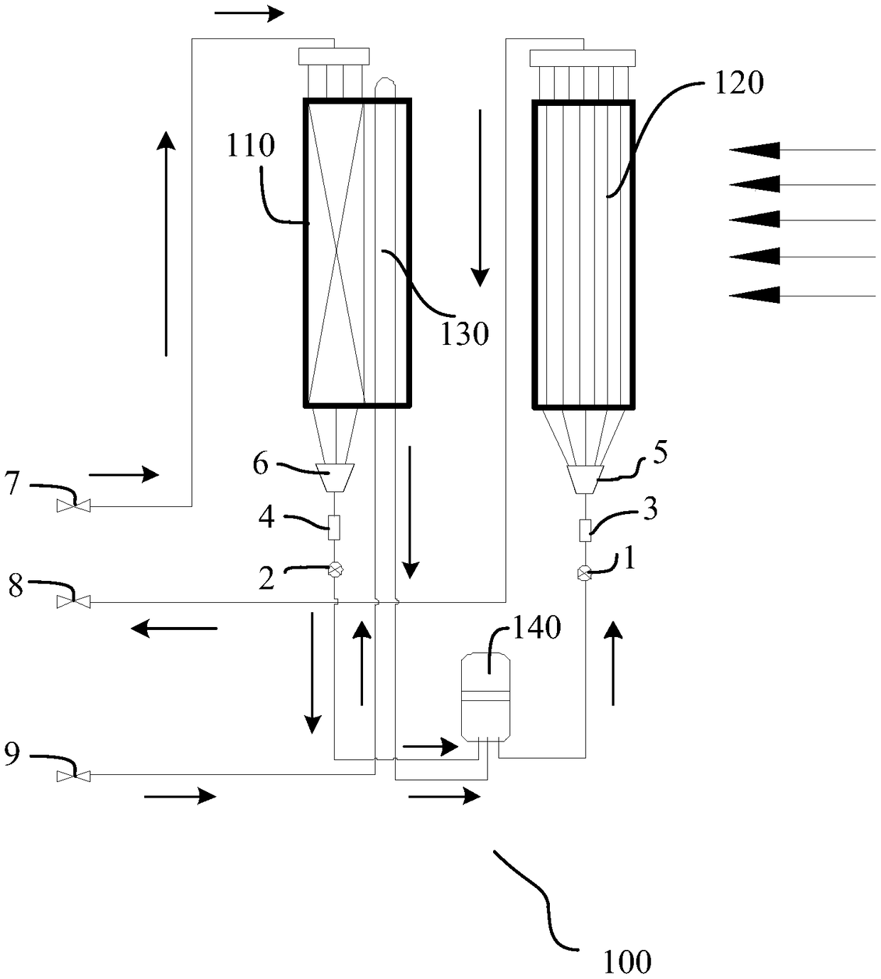
[0030] figure 1 is a schematic diagram of an indoor unit of an air conditioning system according to an embodiment of the present invention. Such as figure 1 As shown, the indoor unit 100 of the air conditioning system according to an embodiment of the present invention includes: a reheater 110 , an indoor u...


PUM


Abstract

The invention discloses an indoor unit of an air conditioning system, a control method and the air conditioning system. The indoor unit of the air conditioning system comprises a reheater, an indoor unit heat exchanger and a heat exchange device. One end of the heat exchange device communicates with a refrigerant outlet of an outdoor unit, and the other end of the heat exchange device communicateswith a refrigerant inlet of the indoor unit heat exchanger and a refrigerant outlet of the reheater. When the indoor unit works in a constant-temperature dehumidification mode, the heat exchange device is used for cooling refrigerant of the refrigerant outlet of the outdoor unit, and then is sent to the indoor unit heat exchanger after being mixed with refrigerant of the refrigerant outlet of thereheater. According to the indoor unit of the air conditioning system provided by the invention, the noise of constant-temperature dehumidification can be effectively reduced, and the constant-temperature dehumidification effect of the indoor unit can also be improved.

Description

technical field [0001] The invention relates to the field of heating equipment, in particular to an indoor unit of an air-conditioning system, a control method and the air-conditioning system. Background technique [0002] In addition to the basic cooling and heating functions, the air conditioner usually also has a dehumidification function. Since there is no essential difference between dehumidification and cooling operation, dehumidification usually causes the room temperature to drop. When the temperature itself is not high and the humidity is high, For example, in the rainy season, dehumidification usually makes the human body feel uncomfortable. Therefore, constant temperature dehumidification technology came into being. [0003] In the related technology, the constant temperature dehumidification technology mainly controls the start and stop of the compressor to ensure the room temperature, and some increase the air temperature of the air conditioner by adding an elec...

Claims


Application Information

Patent Timeline
Patent Type & Authority Applications(China)
IPC IPC(8): F24F1/00F24F3/14F24F11/84F24F13/24F24F13/30F25B40/02F25B41/06F25B49/02F25B41/31
CPCF24F1/0059F24F3/14F24F11/84F24F13/24F24F13/30F25B40/02F25B49/02F25B2500/12F24F2003/1446F24F2013/247F25B41/31
Inventor 李友良李安民郑涛杨斌
Owner GD MIDEA HEATING & VENTILATING EQUIP CO LTD
Features
  • R&D
  • Intellectual Property
  • Life Sciences
  • Materials
  • Tech Scout
  • Unparalleled Data Quality
  • Higher Quality Content
  • 60% Fewer Hallucinations
Learn More